Evaluate panel resonance: contact mic?
Many posts ago someone suggested measuring panel resonance with an accelerometer.
I have been thinking to myself that perhaps one could evaluate panel resonance with a contact mic. That plus REW or the like. Seems like it might be easier / more diy-friendly.
Contact microphone - Wikipedia
I can't quite decide if that would be good enough to be useful, or if there are issues trying to do that. Any thoughts or experience from this bunch?
It depends on what you are trying to achieve. If you stick an accelerometer somewhere on the cabinet you can get some information about the motion at that point on the panel. Depending on what is going on you might see something interesting but it will be pretty incomplete. For example, in Stereophile's loudspeaker measurement sections a signal from an accelerometer is shown which can sometimes provide a bit of qualitative information but it is not particularly useful for making quantitative comparisons.Many posts ago someone suggested measuring panel resonance with an accelerometer.
I have been thinking to myself that perhaps one could evaluate panel resonance with a contact mic. That plus REW or the like. Seems like it might be easier / more diy-friendly.
Contact microphone - Wikipedia
I can't quite decide if that would be good enough to be useful, or if there are issues trying to do that. Any thoughts or experience from this bunch?
In industry what is normally done is to measure panel displacement/velocity/acceleration and phase on a grid of locations covering the whole of the outside of the speaker. Hundreds of locations. If the magnitude and phase of the velocity is known over the whole of a closed boundary then the pressure at the velocity locations can be calculated by solving a boundary integral equation. If the pressure and velocity are known over the whole of a closed boundary then the pressure can be evaluated at any point outside the boundary. This enables the full radiated sound field to be determined up to a frequency set by how closely spaced the points were on the measurement grid.
If you are looking for rough qualitative information then a knuckle rap test could provide it. An accelerometer is likely to have better signal-to-noise but is missing the sound radiation information. Whichever you would need to measured at several locations in order to find the modes which are being energised.
...test results.
Thanks for the reminder of Art's excellent site.
After I reread it I realised there's a bit of discrepancy with Earl's comments.
Earl says the fundamental mode dominates, Art comments that this was not necessarily the case, to his own surprise.
I dimly recall a claim that the Newtonian reaction force of the driver was the main cause of vibrations rather than the air pressure in the enclosure.
I don't recall the author except that it was someone with some credibility, which is why I took note of their claim.
Anyone remember the thread or author?
Best wishes
David
I recently had to do some testing of exciters and plate materials for use as cymatic/chladni plates for an Art museum, and I suppose it might be possible to use a suitable powdered medium like salt or rice to see what happens on speaker box panels (as long as they are flat and horizontal) to test for panel resonances, and then you might be able to see what is and isn't vibrating as you do a frequency sweep.
Cheers, Arthur
Cheers, Arthur
[C]hladni plates...use a suitable powdered medium like salt or rice to see what happens on speaker box panels...
Hi Arthur, that's a really cute idea!
It's a classic physics demonstration but it hadn't occurred to me to use as a speaker test, thanks.
Best wishes
David
..I suppose you could even use a turntable tone arm...
That was an idea that had occurred to me as a cheap way to check cabinet vibration.
But I like your idea to actually see the pattern of vibration, even if it doesn't show phase like an expensive laser scanner.
Best wishes
David
Hi Arthur, that's a really cute idea!
It's a classic physics demonstration but it hadn't occurred to me to use as a speaker test, thanks.
Best wishes
David
I recently had to do some testing of exciters and plate materials for use as cymatic/chladni plates for an Art museum, and I suppose it might be possible to use a suitable powdered medium like salt or rice to see what happens on speaker box panels (as long as they are flat and horizontal) to test for panel resonances, and then you might be able to see what is and isn't vibrating as you do a frequency sweep.
Cheers, Arthur
It works really well, however sound levels can be quite high which can annoy the neighbours! Something with a lower particle mass like crushed glass works well, which is available for craft work in different particle sizes and colours and is not hygroscopic. It certainly tells you where to put the braces!
As an aside, I have always aimed for extreme stiffness in sub enclosures and extreme damping (even at the expense of stiffness) elsewhere, my aim being the absolute minimum of stored energy. It's worked well for me at my level.
Just going on memory, isn't that in the KEF LS50 whitepaper?I dimly recall a claim that the Newtonian reaction force of the driver was the main cause of vibrations rather than the air pressure in the enclosure.
I don't recall the author except that it was someone with some credibility, which is why I took note of their claim.
What's your opinion of using one only for relative comparisons?some guitar pickup is tuned to peak at high frequency.
Don't use it to measure any thing.
...isn't that in the KEF LS50 whitepaper?
My recall is that I read it in posts by "Speaker dave", his bio says he worked for KEF so makes sense it's in that white paper.
Best wishes
David
What's your opinion of using one only for relative comparisons?
I overstated.

Not sure if he was still at KEF for the LS50, but he's definitely made a lot of posts about damping cabinets & decoupling drivers.My recall is that I read it in posts by "Speaker dave", his bio says he worked for KEF so makes sense it's in that white paper.
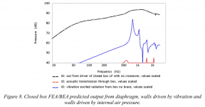
Anyhow, I skimmed the LS50 whitepaper again, and it does cover this well. Their sims indicate that you can ignore air pressure effects until you've decoupled the driver. Example attached. Worth a (re-)read.
Attachments
Not sure if he was still at KEF for the LS50...
Yes, I didn't mean he necessarily was involved with the LS50, just that he was from that school, his posts and the white paper take the same view.
I knew of that paper but never actually tracked it down until now, indeed worth a read.
Best wishes
David
I overstated.
I think it's a fair point to raise and at least check.
Art didn't claim any absolute measurements, used for comparison.
There are not-too-expensive accelerometers available, member "Gdan" sells a kit and can calibrate the accelerometer.
The ACH01 that he uses is ~$50, probably cheaper ones with similar performance are now available - accelerometers have almost become a commodity item.
Best wishes
David
That graft above looks scary.
Most of the radiations happen in the range where our hearing is most sensitive.
Mass Damping
When we add mass to our car, the ride got smoother.
Tall buildings use mass of pendulum to dampen swaying.
Ships use mass of water to dampen rolling.
I call those Mass Damping.
Most of the radiations happen in the range where our hearing is most sensitive.
Mass Damping
When we add mass to our car, the ride got smoother.
Tall buildings use mass of pendulum to dampen swaying.
Ships use mass of water to dampen rolling.
I call those Mass Damping.
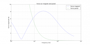
I don't know about people but just about every FE simulation of a speaker cabinet which includes the internal air pressure (it is often dropped) will show it to be small-to-negligible at the frequencies of the lowest cabinet modes compared to the forces from the driver hammering on the baffle. The figure below is from some working notes for a subwoofer with a small sealed cabinet which has perhaps the largest internal forces relative to the forces from the magnet. The resonances start at around 500 Hz but are shifted mainly higher in frequency by various design modifications. The lowest pair of resonances (2 symmetrical modes) are not really driven and would radiate weakly to the listener even if they were. It is the mode above which is the nasty one.Earl says the fundamental mode dominates, Art comments that this was not necessarily the case, to his own surprise.
I dimly recall a claim that the Newtonian reaction force of the driver was the main cause of vibrations rather than the air pressure in the enclosure.
I don't recall the author except that it was someone with some credibility, which is why I took note of their claim.
Anyone remember the thread or author?
BTW speaker dave has worked at plenty of speaker companies but is US based and I don't think he has worked at KEF here in the UK. Andrew Jones used to work at KEF and has posted here about cabinet vibration.
Placing particles on panels to reveal standing wave patterns is of limited practical use. As mentioned by someone above, Earl I think, the lowest and most problematic modes tend to involve the whole speaker bending and not higher order panel vibrations. These obviously do occur but normally at frequencies sufficiently high and weakly driven and/or radiating that they are not a practical problem. An exception might be something like a large thin walled cabinet with no bracing so one cannot be absolute about it.
Attachments
- Home
- Loudspeakers
- Multi-Way
- constrained layer damping with MDF and Ply