I'm not sure if anyone has suggested this one, it was very popular back in the 90's, not sure how many uses it today though.
NoiseKiller Yellow - Vibratec (Engelska)
NoiseKiller Yellow - Vibratec (Engelska)
Do they still sell that stuff? Seems difficult to find anywhere.
I have no idea, probably best to send an email to them and ask.
CLD
For another idea of viscolastic material, you can try Roberts 3095 carpet adhesive. One guy compared this to green glue in a you tube video and it seems to work good, and is a lot cheaper than green glue.
I am attaching a number of papers which research different aspects of CLD.
Retsel
For another idea of viscolastic material, you can try Roberts 3095 carpet adhesive. One guy compared this to green glue in a you tube video and it seems to work good, and is a lot cheaper than green glue.
I am attaching a number of papers which research different aspects of CLD.
Retsel
Attachments
-
1956-Article Text-6905-1-10-20120329.pdf355.9 KB · Views: 100
-
496f908fa76cfd8b4c99426e47625f7bafea.pdf284.4 KB · Views: 75
-
10.1.1.850.8374.pdf292.1 KB · Views: 62
-
dagogo.com-A Whitepaper The Audibility Of Cabinet Panel Resonances and Pat Pend Method Of Reduct.pdf163.8 KB · Views: 106
-
E3170063514.pdf127.5 KB · Views: 68
-
Gries_Dave.pdf591.6 KB · Views: 70
-
Vibro-acoustical analysis and design of a multiple-layer constrai.pdf1.3 MB · Views: 80
Last edited:
Yea, I found these and downloaded them when I was looking into this concept. As Earl said, this is a complicated field. The type and thickness of viscoelastic layer is chosen based not only on the frequency of the sound being targeted, but also by the characteristics of the constraining layers and amount of sound deadening being targeted. For woody materials, you might have to do all new research to optimize the performance of CLD for speakers.
In many of these cases which seek to limit sound transmission, weight is a concern, which likely is not a concern for audio speakers which just sit there.
One strategy might be to use more than one viscoelastic material for a wider range of frequency control. For example, you could use a viscoelastic glue along with some sort of rubber.
Retsel
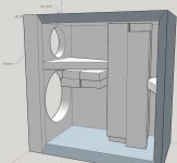
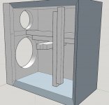
I have been sketching up a 2-way box in Sketchup. After reading Mr. Gedlee his patent and all the tips from this thread. Below you can see the result.
The braces for the top- and bottom panel, as well as the side panels-braces were made from 4 panels. This is done with the thought that the shear dampen forces are now possible in two axes instead of one. To not clutter the box too much, the baffle and backpanel-brace are connected to the other two.
I would really appreciate any feedback on this.
Attachments
Last edited:
Looks like something I once considered. It can be humbling to remember that some resonances can be damped by touching a panel in one place with the tip of a finger.I would really appreciate any feedback on this.
Attachments
Looks like something I once considered. It can be humbling to remember that some resonances can be damped by touching a panel in one place with the tip of a finger.
It looks very sturdy designed. Did this one make it in real/physical life?
You have the right idea, but I don;t see the need for such large braces. The braces act in tension and compression where materails tend to be quite strong. In my speakers the cross braces are only 1" x 1", which is more than enough, especially if they are oak.I have been sketching up a 2-way box in Sketchup. After reading Mr. Gedlee his patent and all the tips from this thread. Below you can see the result.
The braces for the top- and bottom panel, as well as the side panels-braces were made from 4 panels. This is done with the thought that the shear dampen forces are now possible in two axes instead of one. To not clutter the box too much, the baffle and backpanel-brace are connected to the other two.
I would really appreciate any feedback on this.
My approach is this. Think of a strong X-brace from front to back and side to side, but instead of connecting each end to its panel, you double them up along their length with CLD and attach only the "floating" part to the panels. This technique works very well. There should be no connections from any panel to the brace or other panels that do not go through the elastic absorber.
The best place for this brace to attach is in the exact middle of each panel. This offers maximum effect.
It was at this point I said, this is ridiculous....and I committed to building a TL enclosure, and never thought twice about silly cabinet resonances again. xD
So you don't believe that a TL enclosure will have resonances and radiation? I'd suggest that due to their size they would have this problem in spades. Larger panels resonant and radiate more than smaller ones.
Last edited:
Thank you for your feedback.You have the right idea, but I don;t see the need for such large braces. The braces act in tension and compression where materails tend to be quite strong. In my speakers the cross braces are only 1" x 1", which is more than enough, especially if they are oak.
My approach is this. Think of a strong X-brace from front to back and side to side, but instead of connecting each end to its panel, you double them up along their length with CLD and attach only the "floating" part to the panels. This technique works very well. There should be no connections from any panel to the brace or other panels that do not go through the elastic absorber.
The best place for this brace to attach is in the exact middle of each panel. This offers maximum effect.
So you don't believe that a TL enclosure will have resonances and radiation? I'd suggest that due to their size they would have this problem in spades. Larger panels resonant and radiate more than smaller ones.
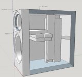
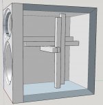
Do you mean this kind of bracing would be enough? (See images below) No braces are touching each other, only the ones in the same axes, but it's hard to see.
And I read earlier you use 2K polyurethane glue as the constraining layer. In the NL we don't have many kinds of this. Would you think this is one would be usefull? http://www.topfproducts.nl/epages/63903627.sf/nl_NL/?ObjectPath=/Shops/63903627/Products/2029-00501
It has these properties:
Crack filling: up to 4 mm
Specific weight: 1.32 g / cm³
Shear strength: 24 N / mm²
Peel strength: 3.1 N / mm²
Viscosity: 60,000 mPa.s.
Temperature resistance: -40 ° C to + 80 ° C
Processing time: 40 minutes
Minimum hardening time for initial strength: 4 hours for 1 N / mm² at 23 ° C
Water resistant
Excellent chemical resistance
Attachments
Also, I see you used the the Melamine Titebond glue, which is available in my country. Would you still reccomend this? And would you use this glue only for in between the braces? Or also to use this to glue the cabinet-walls together?You have the right idea, but I don;t see the need for such large braces. The braces act in tension and compression where materails tend to be quite strong. In my speakers the cross braces are only 1" x 1", which is more than enough, especially if they are oak.
My approach is this. Think of a strong X-brace from front to back and side to side, but instead of connecting each end to its panel, you double them up along their length with CLD and attach only the "floating" part to the panels. This technique works very well. There should be no connections from any panel to the brace or other panels that do not go through the elastic absorber.
The best place for this brace to attach is in the exact middle of each panel. This offers maximum effect.
Last edited:
Do you mean this kind of bracing would be enough? (See images below) No braces are touching each other, only the ones in the same axes, but it's hard to see.
Close. All the braces should be joined together at the center creating a fixed point in three dimensions. Then the legs are isolated from this fixed point.
The panel damping theme has strayed at times into sound containment by the enclosure, which I find faintly comical considering that the only thing stopping unwanted sound coming out of the listening side - the cone - is a piece of thin cardboard...
There is no evidence that sound comes through the cone. The cone is not fixed, but free to move and so sound in the box will move it. But this then shows up in the frequency response of the driver. It is this back pressure that causes the box compliance effect.
ALso any motion of the cone that is not prescribed by the signal is heavily damped by the back EMF effect of the system.
SOund leakage through the cone is not an issue.
Also, I see you used the the Melamine Titebond glue, which is available in my country. Would you still reccomend this? And would you use this glue only for in between the braces? Or also to use this to glue the cabinet-walls together?
I don't recall ever using Titebond, maybe once to try it. I use a two part polyurethane with lots of filler for damping. This stuff is the best damping material that I have ever found.
And I read earlier you use 2K polyurethane glue as the constraining layer. In the NL we don't have many kinds of this. Would you think this is one would be usefull?
Can't say for sure. Try Innovative Polymers, Inc. | IE Series™ Urethane Liquid Plastic :: Shore A
That's what I use. It has to be Shore A.
My poly boards come from Germany, so you should be able to get those in NL.
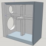
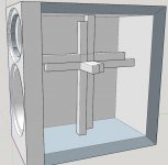
Third time is the charm, hopefully...Close. All the braces should be joined together at the center creating a fixed point in three dimensions. Then the legs are isolated from this fixed point.
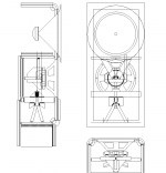
Do you mean this? See below.
Thank you. What should I be looking at exactly? Maximum tensile and tear strength? If so the IE-80A seems excellent.Can't say for sure. Try Innovative Polymers, Inc. | IE Series™ Urethane Liquid Plastic :: Shore A
That's what I use. It has to be Shore A.
My poly boards come from Germany, so you should be able to get those in NL.
Attachments
Who needs evidence? Common sense and experience shows that both would happen.There is no evidence that sound comes through the cone. The cone is not fixed, but free to move and so sound in the box will move it.
- Home
- Loudspeakers
- Multi-Way
- constrained layer damping with MDF and Ply