andy, I see, well said. For your previous post: I would also add more woofer cone area and head for nice loud sound but not sure what to suggest yet since no goal I understandHence throwing out some relevant aspects that are not tied to particular system size, although very relevant to how the size is tied to performance.
AllenB, I'd like to get bottom of it in general so please come forward with hints where to dig out more info on this subject. My thoughts are based on observations on simulations as well as measurements of a prototype system. Oversimplification for sure, but that gives the theoretical best case scenario with and real world systems make it only worse. I have no evidence what amount of diffraction at which frequency is audible and what is not, for example, hence going after minimization which is fine oversimplified. It is easy to sim and measure and evaluate when there is more or less of diffraction interference.
MrHifiTunes, popout any diffraction simulator and experiment with transducer size in relation to baffle size. You'll quickly notice what is baffle step and that there is ripple above that until wavelengts are shorter than the transducer size. This phenomenon looks the same no matter if it is small transducer on small baffle or big on a big baffle. Bandwidt where the ripple happens is directly related to baffle size (giving the low frequency limit, baffle step) and transducer size (high frequencies start to beam), diffraction interference happens on this bandwidth to the listening window. I'm doing it on VituixCAD and have posted many screenshots and texts on the observations so that anyone could check it out. It is most effective to do by your self since it is more real time, you'll see immediately what the trend is when you enlarge or minimize the baffle, or add roundovers and what size roundovers are effective.
Are we not going of topic? This discussion is nice and good, but should be tackled during the project when "wide baffle" alternative design comes along. ppl can give their thoughts and experiences then. How to handle ripple issues etc...
Now we are trying the kick off the project. There was asked for input to outline the project I gave my ideas and interest. Are there more things that needs to be clear before?
Tmuikku,
If wide baffle was an issue, infinite baffle would be a no no especially in pro environnement.
It's a compromise as always. Your view on it is ok given a certain set of constraints, once you've got a different set of constraints it might be different.
Here is an hint about 'wide' baffle: once you are around 50cm width (~250hz) and you have minimum edge diffraction solution implemented (- roundover or slanted-) the diffraction happens on frequency where first reflection, diffraction and direct sound merge ( on 'typical' domestical room) ... no way to differenciate them= no more issues.
Some foods for thoughts ( not nescessarly for you Tmuikku):
Infinite-baffle
Well it is the edge that makes the diffraction happen. At the edge impedance is changed and secondary sound source is generated. This happens in delay, relative to distance from the sound source to the edge, and both the direct sound and sound from the edge (all around!) interferes in the listening window. So, wide baffle is not a problem if the transducer on it is as big.
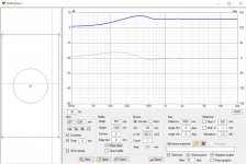
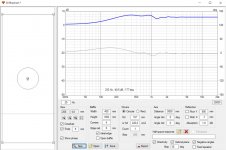
Please download VituixCAD, open up diffraction tool from the tools menu, input baffle width and height and driver SD and hit "New" to see the result. Here is few attached:
1. 15" ideal driver on 550 x 1000mm baffle.
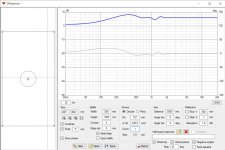
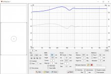
2. 8"
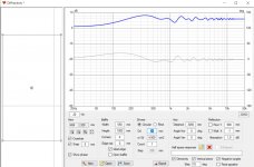
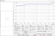
3. 1"
As you see the baffle step frequency, low end of the diffraction interference bandwidth stays at put because it is related to baffle size. The top end moves up in frequency as the transducer gets smaller. This is logical, sound smaller than the transducer gets radiated to the baffle and meets the edge, that is acoustically large enough feature to cause secondary sound source at the edge.
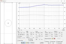
4. Here is 8" driver on minimal baffle. Very little diffraction interference.
5. baffle gets bigger. Notice the baffle step gets lower and the diffracting bandwidth gets wider. The top was defined by the driver size and stays put.
6. even bigger baffle.
7. It takes roundovers starting immediately at the driver edge to remove the diffraction altogether. In this case, 80cm wide baffle roundovers radius 30cm is required because the diffraction is related to baffle size wavelengths and roundovers need to be big in relation to the wavelengths. Hence, widening baffle requires even bigger roundovers for same amount of diffraction.
If reasoning from the observations here one quickly notices diffraction is not problem for woofer since the baffle is often width of the woofer. However if smaller mid and even smaller tweeter are on the same woofer sized baffle the diffraction interference plagues the response. For mid it is roughly wavelengths from the woofer size to the beaming, all of the bandwidth basically. Same for the tweeter, from the xo until beaming.
Note, traditionally this is somewhat mitigated by offsetting the mid and tweeter from the baffle center but his only rotattes the interference out from 0 axis. True, possible to direct out from main listening axis but it doesn't remove the diffraction anywhere. Just tick "Feed driver" and click Export to see the diffraction to any angle in the polar map in the main program.
Attachments
Last edited:
... Are there more things that needs to be clear before?
No just the age old battle where believes, opinions, hobby engineering and science meets
I've been farming on evidence from simulations to make people really think of the stuff and not just accepting what info circulates on the forums. To encourage all of you try stuff out instead of reading, gives a lot more insight. There really is no reason to believe, be believer or not believer, when it is rather easily tested and reasoned on. Alright, carry on with the topic.
Last edited:
I'm not convinced you know the limitations of your simulations. Are you assuming diffraction amounts based on the amount of response change you see? Not taking into account the timing of the diffraction, the relative audibilities, or the other properties which are impacted by it?
We are diving in too deep...
This is food for when the wide baffle comes along.
There are designs issues related to driver, baffle width and radius.
This can be discussed then how to find the optimum. That's the learning process for a newby. If one can learn and understand this, then mission accomplished. If "newby" then thinks that benifits outweigh the downsides, he can build the design which is constructed to the best optimum with the given set of drivers. But all this is future subject.
Now we want to set the lines and scope for this project.
Is there some ground for this approach? Making alternative designs with same set of drivers. For each alternative one can explain how to come to the given build. what are the + and -. because every design is a compromise.
This is exactly what I mean with believers and non believers. I dont judge, Im a newby, I want to learn.
When the subject pop's up with buidling this alterative design..ppl with experience can share their thoughts. I as a newby will make the evaluation if the benefits/down sides are worth the build. But When I built it, I know that the design is made to the best possible given the conditions.
I'm in no way a 'believer', neither is Tmuikku or AllenB from my point of view, we ( at least I but i'm sure they too) try to find answer in science and the fact there is many fields interacting between them ( acoustic, electronic, psychoacoustic,...) which makes a whole view sometimes tricky.
The issue i see is it's a global approach relative to the design criteria and as such a perfectly valid answer in one case will not be in another. That is just my point and why i tease Tmuikku.
Tmuikku approach is valid there is no question about it for me but an other one can be too it will change the constraints and answers and logically the rendering of loudspeakers too.
Tbh, i listen to 'wide' baffle loudspeakers for more than 20years and smaller ones too... I tried to reverse engineering the 'wide' because they had issue and this opened a can of worm as once i discovered where the 'issue' was it opened even more question to me. Which in turn led to be interested in other approach and test and built... it's endless ( and why it's fun).
I'm more or less in agreement with AllenB, there is other points to be taken into account than just the freq where it happen, but it is a different rendering...
Anyway what does matter in my view is to be aware of the issue and taking care of it. The way it's done is a design choice and doesn't matter this much ( to me).
Sorry for the offtopic Mr Hifitunes, but be ready for such things to happen in a group design effort.
Last edited:
AllenB, interference can be inspected in the polar map and other graphs in the main window. Time difference is path difference through the corner to the listening /observation spot). Can't get less time delay than the width of driver surround and rim, around 2cm in average? that 1/4 wavelength of roughly 4kHz so anything below will sum as single source. It is pretty easy to calculate and there is no need to, just inspect the graphs on main program and see the interference to various angles in various frequencies. Make the distance from cone to edge 10cm and the path length difference to 3m listening spot is roughly the same ~10cm, which is 1/4wl of roughly 800Hz, anything above this will have some effect on it depending on which distance you observe (not much difference 3m is much longer than 10cm). Given that the transducer has output on that bandwidth along the baffle.
1kHz is 1ms, ~30cm in distance. Less is less, more is more in this case, it is relative and that is why I'm thinking even if it all is very much simplified it still applies to reality, in relation. I'm not sure if there is some exact delay or frequency where diffraction is not audible, where it would be above or below that. Maybe there is? I'd avoid diffraction where the ear is sensitive, the vocal range.
You are right I'm observing severity of diffraction by the graph and I've written I don't know at which frequency diffraction matters and where not. Only thing I'm saying is to minimize the diffraction interference is to minimize the baffle area around the drivers. Wide baffle yields lots of diffraction interference spanning the whole vocal range at worst, must be more audible than none.
If one plays with the diffraction tool there is not much options to keep the diffraction out from the 1kHz +- few octaves, minimum flat baffle area around drivers
Last edited:
Yeah it shouldn't matter on infinite baffle. I'm generalizing to usual driver and baffle dimensions below roughly < 1m which lay diffraction interference, if any, into the vocal range. It is baffle edge diffraction that makes it severe, it surrounds the drivers and focus the issues on listening window. Mind you every obstacle in the room diffracts sound but there is nothing one can do about it or just take the other stuff out There should be some threads on it I think, I've posted this many times. Well, back to this particular thread and topic shall we!
There should be some threads on it I think, I've posted this many times. Well, back to this particular thread and topic shall we!maybe believers and none believers isn't the right phrasing. English isn't my native tongue. But you have those who see benefit in some design and others see downsides.
Bringing them together and make it a learning process for all would be the benefit from this design. I think all can learn and improve not only the newbies.
Look at English commercial speakers design where they let the cabinet resonate. They see some + in this approach others will see only -'s.
But can we get back on track?
Does it make sense for this approach?
The idea is to go a broad as possible with a given set of drivers. with each alternative design the specific issues can be discussed. How to get around them etc....
I don't know if you still "think" like newbies but most look for a specific design and read the comments how they sound and then decide to build it.
This project would be able to give them some more objective insight on the different variations possible.
does it make sense or am I talking nonsense?
Are there more things needed to set the scope?
Last edited:
Making alternative designs with same set of drivers. For each alternative one can explain how to come to the given build. what are the + and -.
just a suggestion: maybe then it should not be a "reference project" but rather an "experimental project" for practical investigation. I would find this quite interesting. although same set of drivers will not be ideal for all different systems.
No same set of drivers is not ideal for all but that and way to come around it be pointed out.
I wouldn't like it to call experimental or educational or... . This gives the impression that the final design isn't optimised to the max.
In the end the goal should be that all designs brings the best musical performance possible with the given set of drivers. If one like to go further and change the set or some drivers to bring even better performance that's possible but that's phase 2 then.
The idea is also to keep the cost as low as possible.
Maybe active XO can also be part of the project, but I would like to get a passive for each alteration as a minimum.
Some ppl will build many proposed designs during their journey. Others will stick to one. At some point maybe it's better to go active.
But you also feel that this project isn't going to be finished before the end of the year. some things will grow faster then others. A good overview is needed at all time. Also information about specific subjects need to be grouped in 1 place if possible.
Newbies must be able to digest it. If someone has some experience on that its most welcome too.
I use the diffraction performance and preference for wide baffle as vessel to another important lesson. Mind the trade-offs!
Speaker design is full of trade-offs where decision to do one thing will cause other things to happen as trade-off. Thinking what else will happen, if I do this or that, will help immensely in a design process! If thinking that "I do wide baffle since it makes the baffle step compensation easy with passive XO", but never thinking about what the trade-off is one gets unintended consequences that bite back later on.
There is always a trade-off to any decision, you just have to figure out what it is or they are. Figuring out as many as possible will give much better rate to success. Pushing trade-offs to cost or size or audio related stuff that is outside reaching the Goal will yield successful project. Making trade-off in audio, in the goal, will yield problems because now you have to get rid of the trade-off and what is the trade-off for that? Ok, in this case off wide baffle diffraction we get trade-off to cost since the roundovers will do it but are cumbersome to manufacture, not too bad. Or just accept a little diffraction knowingly. The point is, one should know what the trade-offs are and knowingly take the least offensive the goal in mind. For example, if using PA drivers but there is no need for huge SPL the SPL capability can be sacrificed for smaller size or lower low frequency extension.
In addition tuning the baffle step for easy passive correction network a wide baffle is very useful to reduce sound to back of the speaker and as a result there is more sound to the front for same amount of power. This is very good thing as is easy baffle step compensation, but as a trade-off there is worse diffraction performance. Diffraction performance could be eased just by adding huge roundovers, using waveguides, slants and what not. Waveguides or cardioid stuff can be utilized to reduce sound to the back without increasing baffle size and diffraction but these would introduce difficult baffle step correction and harder manufacturing.
While making this kind of thought experiments and decisions for a design one has to remember it is enough to keep problems sufficiently low, I think there is no need to get rid of diffraction completely for example, as it is almost impossible with physical objects. It is just that large roundovers would be hard to manufacture.
When there is a goal for a project, with which stuff can be prioritized like quality / size / cost importance, it is relatively easy to reflect the decisions all the way down from the basic principles and the Goal and knowingly take the right trade-offs. For example, if cost and ease to manufacture is key for given project then slim baffle is a lot better choice than wide simply because it is easier and cost effective. But! Now there is the baffle step possibly on the midrange bandwidth! which is hard to do by passive xo, to span baffle step correction on multiple drivers and we are stuck with diffraction or hard to manufacture roundovers. Or switch to DSP and many problems just go away, with additional cost.
Million things in a design, before single driver needs to be chosen I mentioned few pages back that the concepts are rather simple by them selves but as soon as one starts to connect the dots vast and complex interplay of things unravels. Thinking of the process like this one quickly realizes there is no best speaker in the world, only best speaker for given application!
Speaker design is full of trade-offs where decision to do one thing will cause other things to happen as trade-off. Thinking what else will happen, if I do this or that, will help immensely in a design process! If thinking that "I do wide baffle since it makes the baffle step compensation easy with passive XO", but never thinking about what the trade-off is one gets unintended consequences that bite back later on.
There is always a trade-off to any decision, you just have to figure out what it is or they are. Figuring out as many as possible will give much better rate to success. Pushing trade-offs to cost or size or audio related stuff that is outside reaching the Goal will yield successful project. Making trade-off in audio, in the goal, will yield problems because now you have to get rid of the trade-off and what is the trade-off for that? Ok, in this case off wide baffle diffraction we get trade-off to cost since the roundovers will do it but are cumbersome to manufacture, not too bad. Or just accept a little diffraction knowingly. The point is, one should know what the trade-offs are and knowingly take the least offensive the goal in mind. For example, if using PA drivers but there is no need for huge SPL the SPL capability can be sacrificed for smaller size or lower low frequency extension.
In addition tuning the baffle step for easy passive correction network a wide baffle is very useful to reduce sound to back of the speaker and as a result there is more sound to the front for same amount of power. This is very good thing as is easy baffle step compensation, but as a trade-off there is worse diffraction performance. Diffraction performance could be eased just by adding huge roundovers, using waveguides, slants and what not. Waveguides or cardioid stuff can be utilized to reduce sound to the back without increasing baffle size and diffraction but these would introduce difficult baffle step correction and harder manufacturing.
While making this kind of thought experiments and decisions for a design one has to remember it is enough to keep problems sufficiently low, I think there is no need to get rid of diffraction completely for example, as it is almost impossible with physical objects. It is just that large roundovers would be hard to manufacture.
When there is a goal for a project, with which stuff can be prioritized like quality / size / cost importance, it is relatively easy to reflect the decisions all the way down from the basic principles and the Goal and knowingly take the right trade-offs. For example, if cost and ease to manufacture is key for given project then slim baffle is a lot better choice than wide simply because it is easier and cost effective. But! Now there is the baffle step possibly on the midrange bandwidth! which is hard to do by passive xo, to span baffle step correction on multiple drivers and we are stuck with diffraction or hard to manufacture roundovers. Or switch to DSP and many problems just go away, with additional cost.
Million things in a design, before single driver needs to be chosen
I mentioned few pages back that the concepts are rather simple by them selves but as soon as one starts to connect the dots vast and complex interplay of things unravels. Thinking of the process like this one quickly realizes there is no best speaker in the world, only best speaker for given application!
Last edited:
Here is the secret for best speaker in the world: take all possible trade-offs in the design from audio to size and cost and you have it Then minimize the size and cost, but no compromise was taken on the audio if possible at all. Haven't got that far yet and it might be ugly and not allowed into living room... if one goes this way it is quite natural to land on realm filled with big bass systems, waveguides and DSP.
Then minimize the size and cost, but no compromise was taken on the audio if possible at all. Haven't got that far yet and it might be ugly and not allowed into living room... if one goes this way it is quite natural to land on realm filled with big bass systems, waveguides and DSP.
Last edited:

I guess we need to get backto the compromises at hand and try and get that forward toward a nice outcome. I would suggest for 8-4-1 drivers separate enclosures / structure. This would enable optimizing the system acoustically a bit further than single box could. Assuming no big roundovers or slants are possible for ease of constuct. This 2 or 3 part construct would also enable you to experiment with the filters and bassbox alignments as well as adding more woofers at later date.
I suspect problems and cost for crossover though, so migh be wide baffle for the mid as well to get the bafflestep to a handy frequency. I havent checked moondogs drivers closely yet. I'm sure here we would need passive xo xpert to say a word. If the cost is to be kept down then it is going to be passive xo without too many nice to have parts.
Meanwhile, anyone checked the moondog 8" driver what kind of boxes it suits? Maybe sim if there is an alignment that could be nice half space and another for quarter space enivironment. What is the smallest feasible box for ok bass and how much bigger is needed to take all potential out from the driver?
What do you think MrHifiTunes if we try and make rough guestimate what is possible with moondog drivers and then perhaps go through if there was some other options what would make better experimental set? I think it is important to keep yo motivated and participating? And i think there are people who know lot about drivers like hifijim.
I suspect problems and cost for crossover though, so migh be wide baffle for the mid as well to get the bafflestep to a handy frequency. I havent checked moondogs drivers closely yet. I'm sure here we would need passive xo xpert to say a word. If the cost is to be kept down then it is going to be passive xo without too many nice to have parts.
Meanwhile, anyone checked the moondog 8" driver what kind of boxes it suits? Maybe sim if there is an alignment that could be nice half space and another for quarter space enivironment. What is the smallest feasible box for ok bass and how much bigger is needed to take all potential out from the driver?
What do you think MrHifiTunes if we try and make rough guestimate what is possible with moondog drivers and then perhaps go through if there was some other options what would make better experimental set? I think it is important to keep yo motivated and participating?
And i think there are people who know lot about drivers like hifijim.
Last edited:
Well we need to start somewhere. I'm not sure where this rough guestimate will bring us. The tread started long time ago.
I assume some nice drivers are available now and not back then.
As pointed out before the drivers should be easy to work with so many XO possibilities are possible.
I assume some nice drivers are available now and not back then.
As pointed out before the drivers should be easy to work with so many XO possibilities are possible.
I'll raise a rather large design issue.
Would the midrange be put into a small cup or is it going to be placed in a calculated cavity?
While most midrange drivers go in a small cup or enclosure to maximise the available space for the woofer I usually use a larger midrange enclosure to allow the midrange to "breathe" although most small drivers don't need much more than a litre or two this does sound different to a driver shoved into a quarter litre plastic cup, especially if the desired XO point is going to be around 300Hz.
While wider than perhaps normal for a 200mm woofer I think that 300mm for the box width is reasonable as that allows a good edge chamfer as well as some offset from centre, although I'd take that as exterior dimension using a nominal 16mm wall thickness.
Will the speaker use a grill? Will the speaker use a woollen felt baffle covering if a grill is used.
Perhaps more importantly will the XO be inside the box or separately in its own small enclosure?
I like separate enclosures myself even if I've only done it a few times.
The SBA 861PFCR is a good driver but I feel too large for this projects midrange
- Home
- Loudspeakers
- Multi-Way
- 3-way reference project??