Hello!
I wanted to builds a new loudspeaker with midrange working on an open baffle. I did several research on open baffles, but some of the technical issues still remain obscure to me. One of the obscure thing is how the open baffle determines the driver excursion.
My question is: how should I consider the xmax when choosing my midrange driver? Let us assume that midrange crosses around 300Hz and 3000Hz (old school stuffs!), in such a situation what should I require to my driver in terms of xmax?
I hope somebody out there in the cloud will help me!
Best wishes
Pierre
What's the size of that midrange?
I once played with a naked 12" guitar driver (no baffle) as a mid, it played down to about 300Hz pretty flat without EQ. With help of baffle, this size of mid can do 150~200Hz with little EQ and without any Xmax issue. It barely moves! (OK, that's not a common midrange size...)
In some other cases, I also tried 7" and 8" midrange on OB, played them down to about 200Hz. They produced ear-bleeding SPL (in home use) without any visible excursions.
So I don't see any problem in Xmax of a 300Hz midrange within reasonable size.
In the area above the baffle cut-off frequency the OB's efficiency is actually higher than for closed box, and should provide more SPL for a given excursion than closed box.
You could try Linkwitz' Excel spreadsheet to calculate max SPL.... nice tool.
http://www.linkwitzlab.com/spl_max1.xls
You could try Linkwitz' Excel spreadsheet to calculate max SPL.... nice tool.
http://www.linkwitzlab.com/spl_max1.xls
Hy Guys,
thanks all for your help. The midrange I would like to use is the SEAS MCA15RCY, is the best paper cone ("true") midrange I have auditioned. Low distortion, huge dynamic (high acceleration factor), damned flat from 300 to 8KHz measured 1W/meter on a 40cm baffle! Here it is:
http://www.seas.no/index.php?option=com_content&task=view&id=102&Itemid=124
I intend to use it on a 40cm open baffle, I measured the driver on the baffle from the listening position. It has -3db point around 294Hz, and then it goes down very quickly.
I want to use it with a 12" bass driver in closed box actively driven using the Beringher DCX 2496 xover with which I control xover point, delay and various equalizations. This digital xover is a killer beast.... but only in the bass region! Moreover its functions allow me to set up the bass response I had never the chance to get in the past... in-room linear from 30Hz to 500Hz with an impressive dynamic range.
The roll-off of the SEAS MCA15RCY on the open baffle is already optimal (too good to be true), but since I don't have measuring tools for distortion, I wonder whether I should put an high pass to the midrange to prevent excess excursion. Of course this would require a stepper lowpass on the woofer, but who cares... the DCX 2496 will do it!
Best Wishes
Pierre
Did you measure off-axis? a 5" woofer is acoustically too small for 40cm baffle.
Other thing, did you try to feed it a tone at 100Hz or so (1 octave below your target xo frequency)? And does it produce noise?
Yes I measured the mid from listening position. What do you mean " acoustically too small for 40cm baffle."?
I haven't tried a pure 100Hz tone. I'll do it.
Pierre
The falling response below 300 Hz is purely due to the dipole baffle loss. The driver itself does not work less below - it has to work more!The midrange I would like to use is the SEAS MCA15RCY... I intend to use it on a 40cm open baffle. I measured the driver on the baffle from the listening position. It has -3db point around 294Hz, and then it goes down very quickly.
It is absolutely necessary IMHO. And you will need at least 12 dB/oct.I wonder whether I should put an high pass to the midrange to prevent excess excursion.
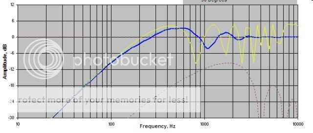
Regarding the baffle width: The diagram below shows the response of a 40 cm wide rectangular OB on axis (green) and at 30 deg (red). A baffle of that width is not optimal above 1 kHz, if constant directivity is a design goal.
Rudolf
Attachments
Very steep roll-off below 300 Hz could be due to the floor reflection. I found that my 8" mid was flat to 100 Hz in a ~40 cm baffle, except for a very large dip at 250-300 Hz. The only cause I found for this was the floor reflection. That's why I decided to cross over the mid at 350 Hz.
Hi Rudolf,
this seems to contradict what have been said in previous posts. I am still confused about the relation: OB vs excursion.
How did you get this simulations? So what would be the optimal baffle width according to your simulation?
The behaviour of OB at high frequency still remains a mystery to me. Troels Gravesen did an "OB study", have a look here:
http://www.troelsgravesen.dk/OBS.htm
In the second part he tries several combinations with the famous Vifa P13WH, well it doesn't have a 40cm baffle, but none of the response I see here are predicted from models. I honestly wonder a bit about the accuracy of the mathematical models for OB.
Best Wishes
Pierre
The falling response below 300 Hz is purely due to the dipole baffle loss. The driver itself does not work less below - it has to work more!
It is absolutely necessary IMHO. And you will need at least 12 dB/oct.
this seems to contradict what have been said in previous posts. I am still confused about the relation: OB vs excursion.
Regarding the baffle width: The diagram below shows the response of a 40 cm wide rectangular OB on axis (green) and at 30 deg (red). A baffle of that width is not optimal above 1 kHz, if constant directivity is a design goal.
Rudolf
How did you get this simulations? So what would be the optimal baffle width according to your simulation?
The behaviour of OB at high frequency still remains a mystery to me. Troels Gravesen did an "OB study", have a look here:
http://www.troelsgravesen.dk/OBS.htm
In the second part he tries several combinations with the famous Vifa P13WH, well it doesn't have a 40cm baffle, but none of the response I see here are predicted from models. I honestly wonder a bit about the accuracy of the mathematical models for OB.
Best Wishes
Pierre
The math for OB is different from box speakers, but has been worked out. You need software if you really want to know what is happening, particularly with cone displacement. The software mentioned above is good, and I use it, but the most comprehensive set of software is MJK's mathcad worksheets (google should find his webpage).
Here is the basic run down for OB - because the back of the driver is open to the air, and is out of phase with the front of the driver, when the two wavefronts meet, they cancel. They meet more at lower frequencies, and less at higher - and once the frequency is high enough, they no longer interact. This leads to two thing - less bass SPL, and irregular off axis response in the highs above the 'baffle peak', the point where the front and back waves are no longer interacting directly.
The frequency of the baffle peak is determined by the baffle size and geometry. This is most effectively predicted by MJK's worksheets. If you want to predict low end response or Xmax limitations, you need to factor the baffle, the drivers area (Sd), and its linear displacement (Xmax). BTW, the free software I've used (excepting Linkwitz's) was fairly inaccurate.
The bottom line is that OB's have greater excursion demands at lower frequencies because the front and back waves are canceling.
Gainphile recommended 40cm is too wide because the baffle peak frequency will be relatively low in frequency, and so the off axis response will suffer above that. Without knowing more about the driver/baffle, 5" is generally too small - it does not have enough excursion and volume displacement to create 'decent' SPL (which depends on how loud you listen). I would guess a 5" driver could only be used down to 400-600Hz, but that is a rough guess.
But people do use 5" drivers or less - but they are listening at relatively low levels, to simpler music, on (much) larger baffles, with much poorer off-axis frequency response (which to me matters a lot). Generally, an 8" mid or larger is necessary if you want decent reproduction between 100-250Hz.
here is a link to MJKs worksheets: http://www.quarter-wave.com/
I can't recommend JohnK's ABCDipole program enough. At $14 it's damn accurate until the 1st peak.
or just use the rule of thumb, baffle width <= 2x driver diameter.
Large baffles will have poor off-axis response, although measured/simulated as flat on-axis. Unless you want a passive system, this is better avoided.
Bass rolloff problem is easily fixed with active xo. Not so with passive.
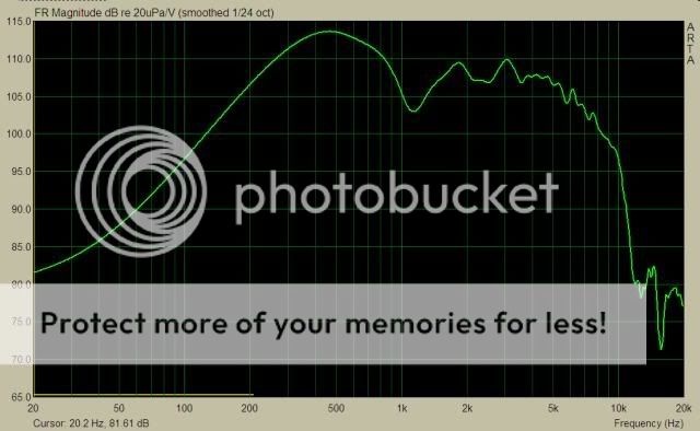
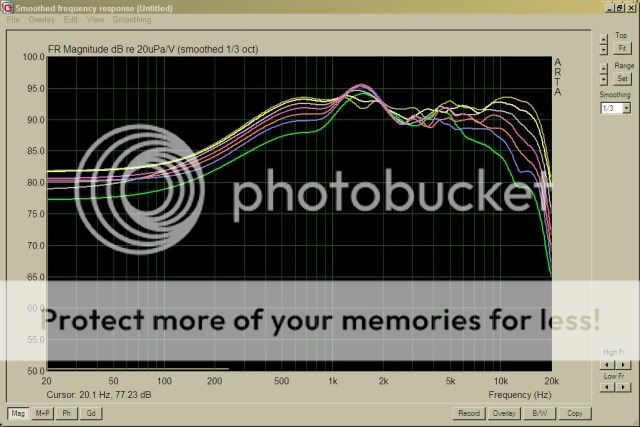
Example of pretty good off -axis response is something like below, an uneq'd measurement. You can see it's nice until 2.5khz or so, and then become really crappy. With large baffle, this will happen very low in the frequency region.
or just use the rule of thumb, baffle width <= 2x driver diameter.
Large baffles will have poor off-axis response, although measured/simulated as flat on-axis. Unless you want a passive system, this is better avoided.
Bass rolloff problem is easily fixed with active xo. Not so with passive.
Example of pretty good off -axis response is something like below, an uneq'd measurement. You can see it's nice until 2.5khz or so, and then become really crappy. With large baffle, this will happen very low in the frequency region.
Pierre,
cuibono has summed the basics of the dipole behaviour pretty well. So I would just like to add some aspects:
1. Regardless of the box (or nobox) type of a loudspeaker project - to keep a given SPL level a driver needs to quadruple its excursion with every halving of its lower frequency limit. In a well designed box-type speaker there will be a frequency, where the spring force of the compressed air on the back side of the cone will limit its excursion. On OB there is no such limitation.
2. Below the lowest dipole peak the SPL will fall off with 6 dB/oct. You need to double the excursion with every halving of the lower frequency limit to keep the same SPL level.
1. and 2. will add. If you know the excursion of your driver in a closed box at e.g. 1 kHz (a frequency where a midrange driver will behave pretty much the same regardless of box or OB) and a specific SPL level, you can easily") calculate the excursion for lower frequencies on OB. You will have noticed that the overwhelmingly dominant factor for the maximal SPL level is your demand for the lower frequency limit.
calculate the excursion for lower frequencies on OB. You will have noticed that the overwhelmingly dominant factor for the maximal SPL level is your demand for the lower frequency limit.
How do you find that lowest dipole peak?
EDGE is a very user friendly simulation program to calculate the behaviour of an open baffle. AFAIK it uses the same Backman algorithm that basicly all other OB simulation programs do. But it does NOT include specific driver TSP! Those have to be superimposed by the user himself.
If you want to minimize your EQ demand, you make the baffle as wide as your wife allows. And forget about constant directivity.
Rudolf
cuibono has summed the basics of the dipole behaviour pretty well. So I would just like to add some aspects:
1. Regardless of the box (or nobox) type of a loudspeaker project - to keep a given SPL level a driver needs to quadruple its excursion with every halving of its lower frequency limit. In a well designed box-type speaker there will be a frequency, where the spring force of the compressed air on the back side of the cone will limit its excursion. On OB there is no such limitation.
2. Below the lowest dipole peak the SPL will fall off with 6 dB/oct. You need to double the excursion with every halving of the lower frequency limit to keep the same SPL level.
1. and 2. will add. If you know the excursion of your driver in a closed box at e.g. 1 kHz (a frequency where a midrange driver will behave pretty much the same regardless of box or OB) and a specific SPL level, you can easily
calculate the excursion for lower frequencies on OB. You will have noticed that the overwhelmingly dominant factor for the maximal SPL level is your demand for the lower frequency limit.How do you find that lowest dipole peak?
EDGE is a very user friendly simulation program to calculate the behaviour of an open baffle. AFAIK it uses the same Backman algorithm that basicly all other OB simulation programs do. But it does NOT include specific driver TSP! Those have to be superimposed by the user himself.
You can gain some SPL with room effects, that will help you. But those are very much determinded by your individual room and speaker positioning.this seems to contradict what have been said in previous posts.
See explanation at the top.I am still confused about the relation: OB vs excursion.
With EDGE.How did you get this simulations?
There is no "optimal baffle" width per se. It completely depends on your individual preferencies. If you strive for best controlled response off axis, as I do, the baffle width has to be small enough to keep the lowest dipole peak at the upper end of the planned passband. This will raise the EQ demand somewhat.So what would be the optimal baffle width according to your simulation?
If you want to minimize your EQ demand, you make the baffle as wide as your wife allows.
And forget about constant directivity.I don't know any models that do account for wings. They are either for flat baffles or for "frames". Keeping this in mind those models seem to be precise enough to me. You should not forget that Troels measurements are not free from room influence.The behaviour of OB at high frequency still remains a mystery to me. Troels Gravesen did an "OB study" ...
In the second part he tries several combinations with the famous Vifa P13WH, well it doesn't have a 40cm baffle, but none of the response I see here are predicted from models. I honestly wonder a bit about the accuracy of the mathematical models for OB.
Rudolf
The falling response below 300 Hz is purely due to the dipole baffle loss. The driver itself does not work less below - it has to work more!
It is absolutely necessary IMHO. And you will need at least 12 dB/oct.
Regarding the baffle width: The diagram below shows the response of a 40 cm wide rectangular OB on axis (green) and at 30 deg (red). A baffle of that width is not optimal above 1 kHz, if constant directivity is a design goal.
Rudolf
Isn't that true?! The green line is typical of the Jamo R 907 Open Baffle with the dip at ~1KHz.
The lowest dipole peak is followed by a dipole dip at twice that frequency. Both are followed by more peaks and dips. Peaks whenever front and back wave are in phase, dips whenever they are 180 deg out of phase. Off axis those peaks and dips occur at different frequencies than on axis:if the baffle is "wide" relative to frequency, it seems that the response drops and becomes ragged.
What causes this?
See Linkwitz:
Isn't that true?! The green line is typical of the Jamo R 907 Open Baffle with the dip at ~1KHz.
That's right. We have tried to explain that for the R 909 at Open Baffle Speakers. Look for reply #4 and 5.
Hi Rudolf,
are you interpreting Linkwitz correctly?
If the baffle gets wider, then the rear radiated path length gets longer. That is not addressed by the graphs you linked to.
When the path length gets longer the first null will be pushed higher in frequency and less deep. That is opposite to your interpretation of Linkwitz.
Please explain further in case my cursory scan of Linkwitz has picked this up incorrectly.
Last edited:
You need to take into account driver's directivity compared to the width in acoustic term.
Quoting the guru himself:
"By making the baffle narrower the transition to the oscillatory region moves higher in frequency, e.g. to above 2000 Hz in the above example. As the driver itself, due to its piston diameter, becomes more directional with increasing frequency, it also illuminates the panel edge with less strength, which then reduces response irregularities caused by diffraction. "
http://linkwitzlab.com/faq.htm#Q8
This is not only a theory but can be done empirically. I've had multiple iteration with my speakers:
P13WH on 45cm baffle:
Look at Johnk's simulator with for the same setup:
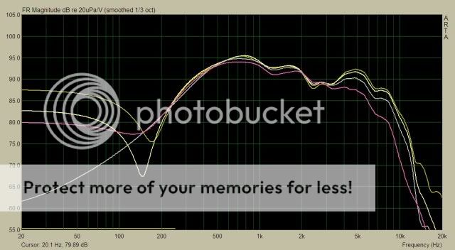
P13WH on 30cm baffle, +tweeters. Note 1kHz region. Basically the baffle is still too large. The tweeters is always the achiless heel of typical dipole setup.
P13WH on 20cm baffle. Smooth up to 2kHz
Quoting the guru himself:
"By making the baffle narrower the transition to the oscillatory region moves higher in frequency, e.g. to above 2000 Hz in the above example. As the driver itself, due to its piston diameter, becomes more directional with increasing frequency, it also illuminates the panel edge with less strength, which then reduces response irregularities caused by diffraction. "
http://linkwitzlab.com/faq.htm#Q8
This is not only a theory but can be done empirically. I've had multiple iteration with my speakers:
P13WH on 45cm baffle:
Look at Johnk's simulator with for the same setup:
P13WH on 30cm baffle, +tweeters. Note 1kHz region. Basically the baffle is still too large. The tweeters is always the achiless heel of typical dipole setup.
P13WH on 20cm baffle. Smooth up to 2kHz
Last edited:
Yepp.Hi Rudolf,
are you interpreting Linkwitz correctly?
If the baffle gets wider, then the rear radiated path length gets longer.
That's right. The graph is only about the dips and peaks and their change with angle.That is not addressed by the graphs you linked to.
In this case it's the other way round.When the path length gets longer the first null will be pushed higher in frequency and less deep.
I am not sure I understand where you want my explanation. So I just did a sim with two different baffle width. Would you mind to guide me to the effects you were writing about - if they show up in the graphs?Please explain further in case my cursory scan of Linkwitz has picked this up incorrectly.
Attachments
If a design goal is best controlled response off axis:
. . and gainphile your rule of thumb: baffle width <= 2x driver diameter is accurate,
which it seems is broadly supported by Rudolf your sims with two different baffle widths for the Vistaon . .
And someone (me) is considering *different midrange drivers,
then am I right that ~ other things being equal ~ smaller mid drivers and smaller baffles push dipole peaks higher, therefore offer better controlled response off axis - over a wider frequency range?
For a dipole system, my situation:
I have a pair of very good “midbass” drivers (97 dB Lambda 15”) which might run up to between 500 – 800 Hz, the crossover frequency to determined by experimenting.
For above them, I had been looking at either:
- 6.5” mids (95 db B&C or PHL that I have, with tweeters above) or
- 6.5” full ranges (eg the 95 db Fostex 166/ 167)
Recently I learnt of the benefits of multiple small drivers, especially lowering driver distortion and less compressed dynamics, and am now considering 8* Fountek 3” drivers, to also give c 96 dB. (As the amp is a 35 watt tube amp, high sensitivity for good overall dynamics is a key design goal).
With 3” drivers instead of 6.5”, if I understand this thread correctly, with the baffle width above the midbass roughly halved: you should get better controlled response off axis, to a higher frequency with (multiple) 3” drivers?
Maybe just horizontally? (to me, that is more important).
I know that a small line of drivers has a different dispersion pattern to a single driver: wider, but less vertical dispersion; and lower drop in SPL in relative to distance,
but (if one can accomodate that, subject to enough Vd) – have I got it right that multiple smaller drivers on a narrower baffle will give better response off axis over a wider frequency range?
Thanks
Last edited:
- Status
- This old topic is closed. If you want to reopen this topic, contact a moderator using the "Report Post" button.
- Home
- Loudspeakers
- Multi-Way
- HELP: xmax and open baffles