Sorry for the basic question but out of dozens of web pages this single element is missing or contradictory in my experience.
Electricity flows from - to + as I understand it. Do I put the inductor/capacitor between negative and the driver OR between positive and the driver?
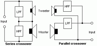
Also, please see attached image. On "input" where is the positive? Top or bottom?
Thanks for any help
Any webpages/links that deal with this specifically are also welcome.
Attachments
SAC said:
Do I put the inductor/capacitor between negative and the driver OR between positive and the driver?
Also, please see attached image. On "input" where is the positive? Top or bottom?
Positive is defined by amp
Series components on positive line
If a paralel curcuit like a zobel(resistor/cap) connect cap to positive and resistor to ground
If you need reversed polarity on a drive, do it after filter
I always do it on filter out, and not on driver terminals
I solid core wire for all connections
I use seperate wire to all drivers, only connected at speaker terminals
http://www.troelsgravesen.dk/coils.htm
Study his site
SAC said:Electricity flows from - to + as I understand it. Do I put the inductor/capacitor between negative and the driver OR between positive and the driver?
You are not working w/DC here but AC.
You are confusing Electron Current flow with Conventional Current flow.
Electron Current flow is based on the movement of electrons which are negatively charge particles. Consequently, in reality, electricity flows from Negative to Positive. This is the model used by electronic techs.
Conventional Current flow says that, from a design perspective, it doesn't matter which way the current is flowing, as long as we adopt and stick to a standard. The conventional standard adopted by electrical engineers is that the Positive (+) terminal is the source of current.
In practice, you simply stick with the convention. The (+) on the amp goes to the (+) on the crossover capacitors and on to the (+) on the speaker.
The flow of actual current doesn't matter. Parts that are polar, have a polar marking, and you uses those (+) and (-) markings consistently through out all your projects.
Just one exception, sometimes for design reasons, a midrange or a tweeter will intensionally be wired backwards. In this case, you somewhat ignore the polarity markings and treat the (-) as if it were the plus. Remember, in a speaker the (+) marking simply determines which way the speaker will move when a positive voltage is applied. As long as, in the final design, the speaker is moving the way it needs to move, you disregard the polarity marking.
So, in designing crossovers, we assume the RED (+) on the amp is the source, and orient all components accordingly.
However, since our signal voltage is swinging through both Plus and Minus, half the time the components are on the wrong side anyway. So, theoretically it shouldn't matter whether the components are in the high side or the low side.
BUT, conventions were established for a reason, and it is best to stick with common conventions so that other people can understand your work.
Steve/bluewizard
Don't think of the + or - in terms of electrons flowing from one to the other, we're talking AC here so it's constantly oscillating back and forth anyway.
What you posted isn't really a circuit diagram - more of a simple figure to illustrate the concept.
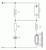
The figure below IS a circuit diagram (taken from http://www.diyaudio.com/forums/showthread.php?postid=1005310#post1005310), and a proper circuit diagram should be like this - with all the polarities marked.
The +'s and -'s are just there to make sure everything is in the right phase, you can reverse everything and it should still work, but follow the circuit diagram exactly and you can't go wrong.
Attachments
Well said.BlueWizard said:BUT, conventions were established for a reason, and it is best to stick with common conventions so that other people can understand your work.
Steve/bluewizard
It will come more naturally with experience, SAC. If you concentrate on physically replicating the schematic diagram's layout with your real components and wire, you'll be well on your way.
SAC said:[
Electricity flows from - to + as I understand it. Do I put the inductor/capacitor between negative and the driver OR between positive and the driver?
In an AC signal the polarity changes hundreds or thousands of times per second. So it hardly matters.
With speakers the "+" means that positive voltage on that speaker terminal drives the cone forward and when the signal reverses the cone is driven backward into the basket. It does not matter much how they are connected but EVERY driver on both left and right need to be connected the same. So a speaker really has no "positve" side. The "+" is just a marker to help you keep the phase corect.
Actually the net flow of current is zero
Yes the physical electrons move the way you describe but engineering convention is to assume the current is positive. Just because we hate to see so many negative numbers
Wow, very informative answers. Thanks.
I was confident enough to wire a first order crossover between my 6ohm visaton b200 and 4ohm BG Neo 3 PDR (back cup removed), just a .4 inductor and a 20mH capacitor. A frequency sweep to my ear showed it to be reasonably flat from mid to highs. An improvement from the shouty highs of the b200 previously.
However, I expected to get 10ohms at least from the circuit but measured closer to six. Is this to be expected???
Must sleep now.
I'm not familiar with those drivers, but how did you wire the crossover (e.g. circuit diagram), and why are you expecting 10 ohms?
If the crossover is wired properly, you should measure the DC resistance of the woofer with a multimeter. It looks like you're getting this, so it's probably normal, but not knowing anything about the crossover it's hard to say.
Sounds like it's a series crossover (correct me if I'm wrong), but if it is, you won't measure the sum of the two impedances because the tweeter should be shorted out by the inductor. If it's parallel, you'll still measure the DC resistance of the woofer only, because the capacitor is effectively an open circuit.
Crossovers separate the high and low frequencies, and DC is as low as they come... so if you're using a multimeter, you'll only measure the low pass side of the crossover.
Hi Stu
I wired the two drivers as in the diagram you attached earlier but with only L1 and C1. I thought the 6ohm driver should be added to the 4ohm driver since they are in series. The shorting idea you mentioned is a new idea to me. This is not as simple as I thought (or hoped)!
I used a multimeter at the inputs. These gave me 5.6ohms. Measuring the low pass section gave 4.3ohms (measured from negative of tweeter to negative going back to amp). Correct so far?
SAC said:I was confident enough to wire a first order crossover between my 6ohm visaton b200 and 4ohm BG Neo 3 PDR (back cup removed), just a .4 inductor and a 20mH capacitor.
Do you mean a 0.4mH inductor (/or a 4mH?) and a 20uF capacitor?
Note: Read here this (white paper) about the BG NEO3 PDR 'arranged as a dipole or semi-dipole with completely or partially opened rear.'
http://www.juoiga.nl/download/neo3pdr_white_paper.pdf
SAC said:Hi Stu
I wired the two drivers as in the diagram you attached earlier but with only L1 and C1. I thought the 6ohm driver should be added to the 4ohm driver since they are in series. The shorting idea you mentioned is a new idea to me. This is not as simple as I thought (or hoped)!
I used a multimeter at the inputs. These gave me 5.6ohms. Measuring the low pass section gave 4.3ohms (measured from negative of tweeter to negative going back to amp). Correct so far?
Unfortunately the theory here can be a little complicated and heavy on the maths - if you're interested, you might want to take a look at some circuit theory textbooks and resources on the internet.
Not sure how much circuit theory you're familiar with, so I'll start with a few basics (sorry if you know any of this already).
These "ohm" values you measure are the ratio of voltage to current through the device. This is the resistance of the device (you may also hear the word impedance - it's technically not the same thing, but for a basic introduction you can consider them to be the same), so something with a high resistance "resists" the flow of current and something with a low resistance allows a high current to flow through it.
Inductors and capacitors have an impedance that varies with the frequency of the signal.
An ideal inductor acts like a short-circuit at low frequencies, as if you just used a piece of wire instead. At high frequencies, it has a very high impedance and "chokes" off the current (you may also hear them called chokes for this reason).
An ideal capacitor does the opposite - for a low frequency signal it doesn't let any current through, but for high frequencies it acts as a short circuit.
That's the way series crossovers work - they short-circuit the drivers at frequencies they aren't supposed to operate. Current takes the path of least resistance, so it bypasses the driver and travels through the inductor or capacitor which is acting as a short-circuit.
4.3 ohms sounds fairly reasonable for the DC resistance of a 6 ohms speaker - but your measurements seem to imply that your inductor has a DC resistance of 1.3 ohms. That's extremely high for a series crossover, in other words it's not doing a very good job at shorting out the tweeter and it's letting frequencies all the way down to zero through. That can damage the tweeter if you're not careful. I try to use inductors with a DC resistance of closer to 0.2 ohms in series crossovers - they use thicker wire and are a fair bit more expensive.
If the speaker sounds good, the component values are probably okay, but you may want to replace the inductor if you are applying reasonable signal levels.
Did you match the sensitivity levels, by the way? That's something else you've got to be careful with when building crossovers.
I can feel a berating coming on. There is not a lot of science in my design. More copying ideas from others and hoping for the best. I've been using the graphic equaliser on my AV reciver and a frequency sweep to rectify problems by ear. Now with the tweeter/xover the high frequency shout is greatly reduced and it is pleasant to listen to without the graphic equaliser.
To rectify, yes it is a 0.4mH inductor and a 20uf capacitor.
The baffle is Jamo 909 style. Approx 46x17inch open baffle with 2xalpha15a and visaton B200 centred above.
The alphas are not connnected yet. I had ideas to parallel them with the BG/B200 2 ways but the unexpectedly low impedance may rule that out. I do not want to run my 41hz Amp6 lower than 4ohms in case I overload it.
A little awkward but I have two 4ohm and two 8ohm alpha 15s.
Might just run the alphas as a mono sub using my av receiver crossover. A little awkward but I have two 4ohm and two 8ohm alpha 15s.
- Status
- This old topic is closed. If you want to reopen this topic, contact a moderator using the "Report Post" button.
- Home
- Loudspeakers
- Multi-Way
- How to wire passive crossover?


