Well, after a long hiatus I am taking to experimenting again. This time I intend to modify my existing OB setup to something more truly constant directivity and power response.
The existing system has 15" 18Sound 15ND930 woofer up to 320 Hz, then a ScanSpeak 8543 up to 1600 Hz, and finally a Seas 27 series dome tweeter. All this on a 48"h, 24"w, and 7" shallow U-baffle without damping, a large panel really.
The plan is to get a CD horn and to convert the midrange to cardioid, probably leaving the woofer in OB. I should point out that after several years of listening to my current setup, I find really nothing much wrong with it, on and off axis balance, imaging, intelligibility are subjectively great, except for one thing: even with toe-in the imaging changes substantially if you move around in the listening position, and sitting off center happens often when watching movies. Plus we moved to a house with a smaller living room so the speakers moved too close to the wall and just look too big there.
Now Earl Geddes in his Summa whitepaper, describes his approach with a fairly narrow CD waveguide with substantial toe-in, to get wide field imaging and optimal small room reverberation, and it all sounded very convincing to me. So I wanted to try this concept with the aim of getting better imaging when off center, and even better power response, and more tolerance for closeness to back wall, as by-products.
I could have bought a Geddes product but I like OB bass, plus, we are DIY here right... so initially I wanted to have an OS CD wave guide a la Geddes CNC machined in wood. But then I thought, let's not vary all parameters at the same time and proceed piece meal. So for the horn I will go for now with the 18Sound XT1086 with an ND1020, both cheap off the shelf items.
That leaves the midrange to fix. It will have to behave like a cardioid on top to mate with the horn, and go towards dipole at the bottom.
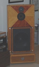
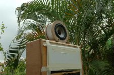
Her is a pic of the existing system, to be modified.
The existing system has 15" 18Sound 15ND930 woofer up to 320 Hz, then a ScanSpeak 8543 up to 1600 Hz, and finally a Seas 27 series dome tweeter. All this on a 48"h, 24"w, and 7" shallow U-baffle without damping, a large panel really.
The plan is to get a CD horn and to convert the midrange to cardioid, probably leaving the woofer in OB. I should point out that after several years of listening to my current setup, I find really nothing much wrong with it, on and off axis balance, imaging, intelligibility are subjectively great, except for one thing: even with toe-in the imaging changes substantially if you move around in the listening position, and sitting off center happens often when watching movies. Plus we moved to a house with a smaller living room so the speakers moved too close to the wall and just look too big there.
Now Earl Geddes in his Summa whitepaper, describes his approach with a fairly narrow CD waveguide with substantial toe-in, to get wide field imaging and optimal small room reverberation, and it all sounded very convincing to me. So I wanted to try this concept with the aim of getting better imaging when off center, and even better power response, and more tolerance for closeness to back wall, as by-products.
I could have bought a Geddes product but I like OB bass, plus, we are DIY here right... so initially I wanted to have an OS CD wave guide a la Geddes CNC machined in wood. But then I thought, let's not vary all parameters at the same time and proceed piece meal. So for the horn I will go for now with the 18Sound XT1086 with an ND1020, both cheap off the shelf items.
That leaves the midrange to fix. It will have to behave like a cardioid on top to mate with the horn, and go towards dipole at the bottom.
Her is a pic of the existing system, to be modified.
Attachments
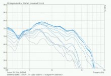
Existing mid polar response
Measurement in the yard, some reflections from plants unavoidable but at least I get the driver 2 m or more off the ground and can use a 2 m measurement distance. Windowed this goes down to 150-200 Hz but unwindowed actually looks better. Arta with Linkwitz mod Panasonic capsule, Rod Elliot's mic preamp modified for the Linkwitz mod mic (...), M-audio Mobile Pre, rather old, and run off the mill laptop.
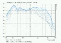
Attached is the ScanSpeak 6.5" 8543 midrange, raw polar response on a mockup 48hx24wx7deep U-frame - basically my existing system. Surprisingly ugly for sounding so good (of course in the actual system I am listening to it is EQ'd reasonably flat, but the polars are no good).
Measurement in the yard, some reflections from plants unavoidable but at least I get the driver 2 m or more off the ground and can use a 2 m measurement distance. Windowed this goes down to 150-200 Hz but unwindowed actually looks better. Arta with Linkwitz mod Panasonic capsule, Rod Elliot's mic preamp modified for the Linkwitz mod mic (...), M-audio Mobile Pre, rather old, and run off the mill laptop.
Attached is the ScanSpeak 6.5" 8543 midrange, raw polar response on a mockup 48hx24wx7deep U-frame - basically my existing system. Surprisingly ugly for sounding so good (of course in the actual system I am listening to it is EQ'd reasonably flat, but the polars are no good).
Attachments
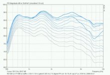
The 18Sound XT1086 with ND1020
And next, the raw polar response of the ND1020 compression driver on the XT1086, mounted on the same mockup 48hx24wx7deep U-frame.
The XT1086 response looks quite respectable to me (must be EQ-d of course). So this is what I have to match with the SS8543 6.5" midrange at say 1200-1800 Hz somewhere.
Edit: the spacing here is 7.5 degrees, all in all 0-90 degrees fontal horizontal polars. On this particular measurement the aberrant 7.5 degree curve is an artefact due to a soundcard timing glitch.
Attachments
How to do a cardioid?
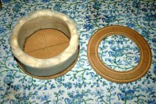
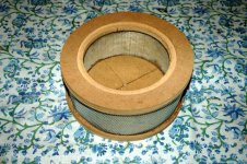
Well, one way to make a driver's response more cardioid like is described here by Siegfried Linkwitz. Basically it consists in putting a flow resistor on the rear of the driver, that acts as a low pass but more to the point, slows down air flow. Linkwitz cites materials that do just that, sintered metal meshes used for exhaust mufflers and filters.
I wanted to try this, but without exotic materials. So I took raw cotton material sold for pillow stuffing (extremely light and fluffy, totally unprocessed) and built something that literally looks like an air filter or a large inside part of a muffler. Front and back to hold the driver, are just routered out of MDF, the cotton is held in place with aluminium mesh. Incidentally I saw a picture of one late model Gradient speaker that seemed to have a construction vaguely like mine here. Looked prettier actually.
Attachments
So let's eliminate the baffle
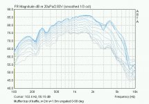
... so I put the muffler assembly on top of the baffle, instead of in it, and measured again. And lo and behold - stunningly regular polars, without crossing lines, without lumpy resonant peaks, none of this stuff. Only drawback is rapid falloff in the bass, due to insufficient separation distance with the rear wave (and low absorption of low frequencies of my damping).
I was quite impressed when I stumbled on this: I really did not do anything very sophisticated here, just added light resistive damping and counterintuitively, a circular, regular, small baffle did the least damage.
Edit: now is this cardioid? Actually polar graphs show, reasonably well above ca. 800 Hz, below that the rear response is less and less damped. I'll post more results tomorrow on the full polars including rear, and FR changes with baffle shapes and sizes.
Attachments
Now that we saw the polars of the muffled driver compared to a large open baffle a number of next questions arise:
1- let's see the rear radiation (full polars) - it could look like anything from omni transitioning to directional regime, to open baffle, to cardioid-like
2- how do baffle size and shape change the picture assuming we leave the muffler as-is?
3- if this was just an open baffle, say a U-baffle, with similar separation distance front to rear, how would this be different?
4- if this was acting more like a "transmission line" (a damped but open box, also see current "Beyond the Ariel" discussion, say this post by Lynn Olson .
To address 1- see pic attached: sonogram shows rear radiation is indeed mostly absent, not perfectly so, but largely 6+ dB down in the range that interests me, i.e., 300-2000 Hz at most.
To address 2- I used bafle templates attached to the front of the muffler.
To address 3- I put the driver on top of a naked PVC pipe of driver diameter, 6.5", and 3" depth (as deep as the driver itself).
To address 4- I closed off the sides o the muffler, leaving only rear ventilation holes (stuffing othewise identical).
Attachments
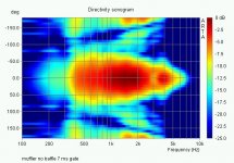
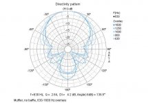
Selected full polars of naked muffler. One could call it a strongly damped asymmetrical double-8 (dipole) pattern ith the rear lobe 12 dB down over most of the range, or an imperfect cardioid. Interestingly, the rear "blade" of radiation at -180 degrees is strongest at higher (1600 Hz here), not at medium frequencies.
Attachments
Thanks for the interest! - Gating is 5 to 7 ms for the polars, that is the best I can get even with x=2m and h=2m measurement height and distance.
I measure outdoors and for the FR graphs I realized that it was better w/o gating because gating decreases the frequency resolution so much. Outdoors the first reflection is the floor bounce on grass, it's visible around 300 Hz as a dip and bump. There will be wiggles caused by plants as well but nothing serious.
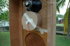
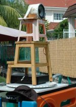
Below a pic of rotating table, graduated in 5 and 7.5 degrees, base is plywood and rotating mechanism is a lazy Susan assembly that I found for USD10")
I measure outdoors and for the FR graphs I realized that it was better w/o gating because gating decreases the frequency resolution so much. Outdoors the first reflection is the floor bounce on grass, it's visible around 300 Hz as a dip and bump. There will be wiggles caused by plants as well but nothing serious.
Below a pic of rotating table, graduated in 5 and 7.5 degrees, base is plywood and rotating mechanism is a lazy Susan assembly that I found for USD10
Attachments
The pic in post 15 shows the PVC pipe assembly BTW, a damped version which I also tried. But first things first, placing increasing baffle sizes (thin circular cutouts taped to front of muffler), what FR do we get?
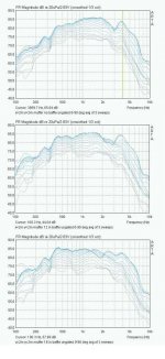
Here is a combo of naked muffler - 12" baffle - 16" baffle FRs. The polars look less clean and at HF curves start to invert (off axis higher than on axis). The low end is lifted due to increased dipole separation distance, but at the price of a bump, described by Linkwitz here .
But still: the muffler improves a lot on the Linkwitz picture above (he uses a 16 in diameter baffle, so compare with the 16 in baffle FR graph attached, bottom). The resonant bump around 400 Hz is less pronounced, and e get no nulls higher up, just smooth on and off axis FR. The graphs of course are completely unequalized.
Attachments
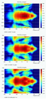
And how does the full +-180 degree sonogram look like? It looks as though a larger baffle makes the rear lobe increasingly stronger, i.e., the baffle dipole separation mechanics take over the muffler flow resistance effects. Picture, sonograms of naked muffler vs muffler with 12" baffle vs muffler with 16" baffle.
Attachments
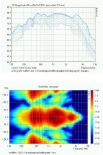
And how does the recommended rectangular baffle fare (to smooth out the separation distance)? I say, not very good. The FR is actually more uneven than that of a circular baffle, we see dips as well now, and rear lobe is strong.
Pic is FR and sonogram of an assembly with muffler, with frontal baffle of 12x21.5", a typical bookshelf speaker size.
Pic is FR and sonogram of an assembly with muffler, with frontal baffle of 12x21.5", a typical bookshelf speaker size.
Attachments
Yeah, apologies btw for dumping all this at once, but I was trying to present a useful, i.e., coherent picture. So after many months of thinking about it and weeks of measurements finally I am getting towards some understanding, but to explain it it takes a lot of graphs
A smaller driver would become directional later. Say you see the lines diverge after 1600 Hz or so in the FR graph. That is the driver becoming more directional by itself. This starts at about 800 Hz already, pics to this effect to follow, in the graphs of the muffled driver the cardioid pattern actually masks this and makes the driver more even in its radiation pattern/power response, which is the point. A smaller driver would have FR lines widening (i.e., directivity narrowing) higher up in frequency by a ratio of (my driver = 6.5" diameter) / (your driver diameter).
Let me first address question 3- above. Just now we addressed Q 2- , what if we keep the muffler and increase separation distance. Now in Q 3- we want to know, what happens if we keep the separation distance and add a muffler. I did this using a 6.5" dia tube, 3" deep, as an "U" baffle, and compared it to the muffler with a 12" circular baffle in front. This is about equivalent to a "flattened" 3" deep tube in separation distance: 6.5+2x3" =12.5". I did that instead of just a flat circular baffle because Linkwitz showed that version already and it's not all that great, uneven and with sharp dips.
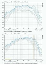
The graphs attached show muffler with 12" baffle (top) vs. no muffler, driver on undamped 3" long PVC tube of driver diameter (similar separation distance). The tube looks much more "dipole-like" in that the directivity is not constant, widens first then narrow, and is generally uneven. No obvious 1/4 effects observed btw, the tube is too shallow w.r.t. frequency band and its diameter as well is large w.r.t. its depth. I should note I tried to add damping to the tube by adding a length of cotton filled tube, 1" and 3", but this made things worse, I started seeing 1/4 resonances (not shown).
A smaller driver would become directional later. Say you see the lines diverge after 1600 Hz or so in the FR graph. That is the driver becoming more directional by itself. This starts at about 800 Hz already, pics to this effect to follow, in the graphs of the muffled driver the cardioid pattern actually masks this and makes the driver more even in its radiation pattern/power response, which is the point. A smaller driver would have FR lines widening (i.e., directivity narrowing) higher up in frequency by a ratio of (my driver = 6.5" diameter) / (your driver diameter).
Let me first address question 3- above. Just now we addressed Q 2- , what if we keep the muffler and increase separation distance. Now in Q 3- we want to know, what happens if we keep the separation distance and add a muffler. I did this using a 6.5" dia tube, 3" deep, as an "U" baffle, and compared it to the muffler with a 12" circular baffle in front. This is about equivalent to a "flattened" 3" deep tube in separation distance: 6.5+2x3" =12.5". I did that instead of just a flat circular baffle because Linkwitz showed that version already and it's not all that great, uneven and with sharp dips.
The graphs attached show muffler with 12" baffle (top) vs. no muffler, driver on undamped 3" long PVC tube of driver diameter (similar separation distance). The tube looks much more "dipole-like" in that the directivity is not constant, widens first then narrow, and is generally uneven. No obvious 1/4 effects observed btw, the tube is too shallow w.r.t. frequency band and its diameter as well is large w.r.t. its depth. I should note I tried to add damping to the tube by adding a length of cotton filled tube, 1" and 3", but this made things worse, I started seeing 1/4 resonances (not shown).
Attachments
- Status
- This old topic is closed. If you want to reopen this topic, contact a moderator using the "Report Post" button.
- Home
- Loudspeakers
- Multi-Way
- Adventures in cardioid