Dear Sirs,
Spend a day drawing and this is what I've come up with;
anyone care to give comments on it ?
Maybe someone can sim the TL-part ?
(please ?)
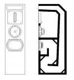
This is what it's supposed to be:
Low driver: KEF B139 SP1044
Mid driver: HEMP FR8c, whizzer removed
Tweet: Stage Accompany SA8525 (6" ribbon)
I know about the difference in sensitivity,
but the plan eventually is to bi-amp it all
Mid & top are in a sealed section, 36 ltr.
woofer's first section is 8,5 ltr.
line's CS starts @ 430cm2, terminates @176cm2
line length = 240cm
What's your opinion ?
any sugestions regarding stuffing ?
Hit me with some constructive critisism !
thank you very much !
")
Empee
KEF B130 SP1044 data:
Fs 25Hz
Qes 0.4
Qms 5.5
Qts 0.3729
Vas 164 ltr
Disp.area 354cm2
Spend a day drawing and this is what I've come up with;
anyone care to give comments on it ?
Maybe someone can sim the TL-part ?
(please ?)
This is what it's supposed to be:
Low driver: KEF B139 SP1044
Mid driver: HEMP FR8c, whizzer removed
Tweet: Stage Accompany SA8525 (6" ribbon)
I know about the difference in sensitivity,
but the plan eventually is to bi-amp it all
Mid & top are in a sealed section, 36 ltr.
woofer's first section is 8,5 ltr.
line's CS starts @ 430cm2, terminates @176cm2
line length = 240cm
What's your opinion ?
any sugestions regarding stuffing ?
Hit me with some constructive critisism !
thank you very much !
Empee
KEF B130 SP1044 data:
Fs 25Hz
Qes 0.4
Qms 5.5
Qts 0.3729
Vas 164 ltr
Disp.area 354cm2
Attachments
Oh, sorry,
I see I wrote B130 but it should be B139...
These are the B139 SP1044 data:
Model: B139
Type: SP1044
Nominal imp. 8 ohms
Freq. range 25-500Hz
Sensitivity: 87 dB
Net weigth: 3.72kg
Closed box volume: 30-60ltr.
Reflex box volume: 60-140ltr.
power handling continues 28.7V rms
Power handling programme 100W
Flux density 0.85T
Total flux: 1.1mWb
Voice coil diameter 52mm
Max. continuous temp. 230 C
Max. internittent temp. 300 C
Thermal time constant 13.7s
Input Impedance R(E) 7.2 ohms
L(E) 1.04 mH
L(e) 0.97 mH
R(e) 4.87 ohms
R(ES) 110 ohms
L(CES) 116 mH
C(MES) 349 uF
Effective diaphragm area 349 cm2
Lineair excursion (pk-pk) 7 mm
Damage limited excursion (pk-pk) 12 mm
Effective moving mass M(MS) 54 g
Suspension Mechanical resistance R(MS) 1.43 mech ohms
Suspension compliance C(MS) 7.43x10E-4 m/N
Compliance equiv. vol. V(AS) 127 ltr
Free air resonance freq. f(S) 25 Hz
Force factor Bl 12.5 N/A
Damping factors Mechanical Q(M) 6.0
Electrical Q(E) 0.39
Total Q(T) 0.37
That's all I could find....
Cheers !
Empee
The lazy way to do a B139 TL would be to use the line dimensions of the B139 TL that Scott & i did. 2 different realizations are shown here:
http://t-linespeakers.org/projects/vProjects.html
There are a ton of possible variations.
Your end-loaded line doesn't take advantage of one of the most powerful tools used in a modern TL -- the offset driver.
dave
http://t-linespeakers.org/projects/vProjects.html
There are a ton of possible variations.
Your end-loaded line doesn't take advantage of one of the most powerful tools used in a modern TL -- the offset driver.
dave
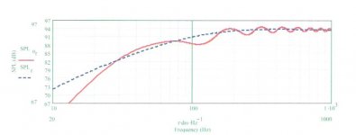
Here's what I modeled
The attached graph shows what I modeled for your TL with the B139 specs you listed. It's not an absolutely exact model, but it's close enough to see its shortcomings. I modeled with a stuffing density of 0.5 lbs/cu.ft. with the stuffing distributed throughout the line's whole length. This isn't necessarily the optimum amount of stuffing. As Dave said in his post, the driver's location at the beginning of the line is not good and the big dip in the response at about 120 Hz is the result of the driver's location. Moving the driver so it would be located at about 20% of the line's length from the closed end would be a big improvement. However, there are other problems to overcome, like getting rid of all those ripples in the response. These can be mitigated by increasing stuffing density and/or increasing the taper. Doing the first will just further kill the bass response, which is already weak, IMO. Doing the second will have the same effect because it will make the line's effective length longer, and the line is already too long making the 1/4-wavelength resonant frequency too low (it's about 20 Hz and probably ought to be more like 28-30 Hz). Dave also mentioned some TLs he's designed for this driver which would be more appropriate. I'll play around my self to see what I can come up with.
The attached graph shows what I modeled for your TL with the B139 specs you listed. It's not an absolutely exact model, but it's close enough to see its shortcomings. I modeled with a stuffing density of 0.5 lbs/cu.ft. with the stuffing distributed throughout the line's whole length. This isn't necessarily the optimum amount of stuffing. As Dave said in his post, the driver's location at the beginning of the line is not good and the big dip in the response at about 120 Hz is the result of the driver's location. Moving the driver so it would be located at about 20% of the line's length from the closed end would be a big improvement. However, there are other problems to overcome, like getting rid of all those ripples in the response. These can be mitigated by increasing stuffing density and/or increasing the taper. Doing the first will just further kill the bass response, which is already weak, IMO. Doing the second will have the same effect because it will make the line's effective length longer, and the line is already too long making the 1/4-wavelength resonant frequency too low (it's about 20 Hz and probably ought to be more like 28-30 Hz). Dave also mentioned some TLs he's designed for this driver which would be more appropriate. I'll play around my self to see what I can come up with.
Attachments
Re: Here's what I modeled
Scott did the TL design, i instigated it, and did all the drawings.
This TL gets an anechoic F10 of just over 20 Hz, and was designed with a fairly gentle roll-off to better match room gain.
dave
pkitt said:Dave also mentioned some TLs he's designed for this driver which would be more appropriate. I'll play around my self to see what I can come up with.
Scott did the TL design, i instigated it, and did all the drawings.
This TL gets an anechoic F10 of just over 20 Hz, and was designed with a fairly gentle roll-off to better match room gain.
dave
Hi Pkitt,
Thanks a lot for simming it !
well, I guess this isn't the optimal design for a B139,
so it's off to the drawingboard again...
No problem but it might take some days 'till I find the time.
In the meantime, let's try a bit of that lazy way;
Hi Planet 10 !
in your (and Scott's) TTL design, what are:
The line length
The starting CSA
The terminal CSA
The driver's location in the pipe ?
I could try to implement these four numbers in my re-drawn design !
BTW, that's how I came up with this design,
only I used the line-characteristics of Dr. Bailey's S.O.T.A.
Naturatly, I didn't get it exact so that's probably why my design
is not so state-of-the-art.....
Thanks a lot guys....
Empee
planet10 said:Another thot -- you don't really want to try to use a B139 much above 250 Hz due to its breakup modes. You'll want to bi-amp right from the start with XO this low,
Check !!
I allready planned bi-amping this thing,
XO'ing @ somewhere like 80Hz to 100Hz
That's why the cab for the Hempster FR8c is fairly large
planet10 said:and you'll want to set the exact XO point/box width to coincide for baffle step considerations.
dave
That thing about "baffle step" I still do not understand.
Do you know a good site or older topic / post where I can find out more about it ?
Empee said:in your (and Scott's) TTL design, what are:
The line length
The starting CSA
The terminal CSA
The driver's location in the pipe ?
96" line, So = 124 in^2, Sl = 21 in^2, Zd = 32.25" (6:1 taper)
BTW, that's how I came up with this design,
only I used the line-characteristics of Dr. Bailey's S.O.T.A.
We've come a long ways since then...
dave
Empee said:That thing about "baffle step" I still do not understand.
Do you know a good site or older topic / post where I can find out more about it ?
You'd need a really wide baffle to XO as low as you plan... i'd let the B139s range a bit higher. With a guess on your 1st sketch width, you'd want to XO at 250-300 Hz.
http://www.t-linespeakers.org/tech/bafflestep/intro-bds.html
dave
planet10 said:96" line, So = 124 in^2, Sl = 21 in^2, Zd = 32.25" (6:1 taper)
gracias !!
....See the results in a few days from now....
planet10 said:You'd need a really wide baffle to XO as low as you plan... i'd let the B139s range a bit higher. With a guess on your 1st sketch width, you'd want to XO at 250-300 Hz.
Baffle width is 35cm (13,78").
How wide should my baffle be if XO'd @ 100Hz ?
I'll look into the BS on your site, it's time to learn something !
(that's Baffle Step, NOT your site being full of B.S.)
Thanks a lot,
again....
Empee

Empee said:Baffle width is 35cm (13,78").
How wide should my baffle be if XO'd @ 100Hz ?
That baffle has a nominal F3 of just above 300 Hz, you want to XO the woofer a bit lower than that, so it is close -- or mount the woofer on the side with width > depth.
dave
Just to expand slightly on what Dave mentioned, -3db frequency caused by baffle step loss may be simply described as occuring at 4560 / baffle width in inches. ~18.25in would be needed to push it down to 250Hz. As an aside, GM & I often advocate (if space & other practical concerns allow) baffles of around 30in in diameter, which ensures that losses are pushed well down into the regions of room gain (& certainly cab. gain), so one tends to cancel out the other.
The aformentioned B139 lines should give you a good starting point; they're deliberately a fairly mild taper & damping (working on the assumption that the 139 will be crossed over relatively low down, and to keep distortion low). You can adjust the stuffing to suit yourself of course, and the material you're using.
The aformentioned B139 lines should give you a good starting point; they're deliberately a fairly mild taper & damping (working on the assumption that the 139 will be crossed over relatively low down, and to keep distortion low). You can adjust the stuffing to suit yourself of course, and the material you're using.
planet10 said:or mount the woofer on the side with width > depth.
I don't want the woofer on the side panel,
so I'd better widen the front...
Hi !
I read a lot today and I think I got the basics of baffle step…
From what I understand, what you suggested was to design the baffle so that the baffle step
was at the exact same point of the XO, so to have no correction needed but the overall gain
(sensitivity) of the low vs. the mid/high amplifier.
But what I think now, is this:
What If I still choose to keep the baffle @ 350mm wide, and actively crossed at 100Hz, I deliberate
choose for lower sensitivity in the low end, and shift the baffle-step problem to the midrange driver.
Sure, I’d still have a rising response in the low end since the baffle step is only a good octave away,
so in practice a 24dB XO slope will behave something like a 18dB XO slope up until 330Hz,
after that returning to 24dB/oct. action.
For the mid-driver, I could compensate (correct) the baffle step diffraction, whether active or passive (to-be-defined).
Reason for me clinging to the low XO of 100Hz, is the comment of the well-respected Mr. Olson, stating:
I really think that 250Hz is a compromise too big, and building a baffle for a 100Hz step would be ~45” in diameter !
if I would go for something that size I’d go for an open baffle altogether.
Am I completely off ?
Interesting stuff, this Baffle Step matter !
Empee
I read a lot today and I think I got the basics of baffle step…
From what I understand, what you suggested was to design the baffle so that the baffle step
was at the exact same point of the XO, so to have no correction needed but the overall gain
(sensitivity) of the low vs. the mid/high amplifier.
But what I think now, is this:
What If I still choose to keep the baffle @ 350mm wide, and actively crossed at 100Hz, I deliberate
choose for lower sensitivity in the low end, and shift the baffle-step problem to the midrange driver.
Sure, I’d still have a rising response in the low end since the baffle step is only a good octave away,
so in practice a 24dB XO slope will behave something like a 18dB XO slope up until 330Hz,
after that returning to 24dB/oct. action.
For the mid-driver, I could compensate (correct) the baffle step diffraction, whether active or passive (to-be-defined).
Reason for me clinging to the low XO of 100Hz, is the comment of the well-respected Mr. Olson, stating:
“My first speaker system, the Audionics TLM-200, used the KEF B-139 expanded-foam bass driver, which has a big peak around 1.5kHz. Even with a 12dB/octave 160Hz crossover, I could still hear the forwardness of the KEF B-139, even though the peak was being attenuated by a good 30 to 35dB by the time we got to 1.5kHz. It took a third-order crossover to remove it from audibility; that moved the peak 50dB down from the rest of the system response.”
source: http://www.audiokit.it/itaeng/KitDiffusori/ARIEL/ArielGoodBass.htm
I really think that 250Hz is a compromise too big, and building a baffle for a 100Hz step would be ~45” in diameter !
if I would go for something that size I’d go for an open baffle altogether.
Am I completely off ?
Interesting stuff, this Baffle Step matter !
Empee
Hi !
I got a bit further on my design.
Since no-one anwered my question regarding the Baffle Step,
I assumed I am right about it (you would've said otherwise, wouldn't you ?)
The plan is to XO @ 100Hz, maybe 120Hz,
correcting Baffle Step in the midrange driver.
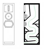
Please take a look at my new drawing.
I tried very hard to use the TTL-dimensions by P10 & Scott,
but it turned out a wee bit different....
Anyone care to coment on this take ?
(green)Line = 2258mm (88,9")
Zd = 715mm from closed end (28,1")
So = 800cm^2 (124 in^2)
Sl = 135.5cm^2 (21 in^2)
I really hope someone will give his or hers comments
Cheers,
Empee
I got a bit further on my design.
Since no-one anwered my question regarding the Baffle Step,
I assumed I am right about it (you would've said otherwise, wouldn't you ?)
The plan is to XO @ 100Hz, maybe 120Hz,
correcting Baffle Step in the midrange driver.
Please take a look at my new drawing.
I tried very hard to use the TTL-dimensions by P10 & Scott,
but it turned out a wee bit different....
Anyone care to coment on this take ?
(green)Line = 2258mm (88,9")
Zd = 715mm from closed end (28,1")
So = 800cm^2 (124 in^2)
Sl = 135.5cm^2 (21 in^2)
I really hope someone will give his or hers comments
Cheers,
Empee
Attachments
Greets!
No, the wider the baffle, the less sensitive to in-room positioning it is.
Assuming the driver's specs are close and at least a 24 dB/octave filter is used, it's fine; otherwise tuning it higher to allow for the Fb downward shift due to a high stuffing density may be better overall.
Really, nicely stuffed, this driver needs ~13-14 ft^3 to get solid, smooth output to 25 Hz, so as always in TL/TQWT/horn design, BIB rules...........
GM
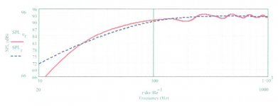
Here's what I modeled...
Okay, Empee, using your most recent TL design, the attachment shows what I modeled for it using Martin King's software. I arbitrarily modeled with 0.5 ohms in series with the driver and used a stuffing density of 0.5 lb/cu.ft. for the whole line's length. As you can (hopefully) see from the response curve, F3 is right about 70 Hz. The system tuning appears to be about 18 Hz, probably a bit low, and you likely could benefit from a larger cabinet as GM suggests.
Okay, Empee, using your most recent TL design, the attachment shows what I modeled for it using Martin King's software. I arbitrarily modeled with 0.5 ohms in series with the driver and used a stuffing density of 0.5 lb/cu.ft. for the whole line's length. As you can (hopefully) see from the response curve, F3 is right about 70 Hz. The system tuning appears to be about 18 Hz, probably a bit low, and you likely could benefit from a larger cabinet as GM suggests.
Attachments
- Status
- This old topic is closed. If you want to reopen this topic, contact a moderator using the "Report Post" button.
- Home
- Loudspeakers
- Multi-Way
- Made up a TL design... any comments ?