It seems to be a piece of cloth glued on a paper structure... i'm curious to know how it is possible to stretch the tissue without deform the structure too muchNice
Could you make a quick summary of the building method & materials in english, here ?
BR
Jean-Louis

Folded Horn Design
Hi everyone!
I am new in horn design, I am more oriented to the room acoustics, and I have two question!
What is this horn type?
How to design this folded horn, mathematically from star to end (eny reference book or paper)?
This is example of folded horn Carvin Vega subwoofer...
Thanks in advance!
Hi everyone!
I am new in horn design, I am more oriented to the room acoustics, and I have two question!
What is this horn type?
An externally hosted image should be here but it was not working when we last tested it.
How to design this folded horn, mathematically from star to end (eny reference book or paper)?
This is example of folded horn Carvin Vega subwoofer...
Thanks in advance!
I suggest designing as a straight horn first using Hornresp (you will find a thread on it here).
Once you have it designed as a straight horn you will have the cross sectional area versus length dimensions.
You can then figure out how to fold it efficiently into the target volume.
Try to keep the bends as smooth as possible (use curved pieces) especially at the beginning of the horn.
Once you have it designed as a straight horn you will have the cross sectional area versus length dimensions.
You can then figure out how to fold it efficiently into the target volume.
Try to keep the bends as smooth as possible (use curved pieces) especially at the beginning of the horn.
The Cerwin-Vega earthquake horn. EL-36C CERWIN VEGA FOLDED HORN SERIES SPEAKERS SUBWOOFERS
It is most probably a front loaded exponential horn.
Designing horns is great fun. I spend most of my free time doing it. Building horns are much more fun though. Decide on a budget. Find plans that fit your budget. Get the components and start building.
But first you need to decide if you want front or backloaded horns. This will certainly set you back a year or two.")
It is most probably a front loaded exponential horn.
Designing horns is great fun. I spend most of my free time doing it. Building horns are much more fun though. Decide on a budget. Find plans that fit your budget. Get the components and start building.
But first you need to decide if you want front or backloaded horns. This will certainly set you back a year or two.
I have found the spreadsheet. But it has Old_calculation and New_calculation
The trick is that the new_calculation is dated 2007 and the old one -2009
Here are the pictures.
Does anybody know where is the new one or the right one?
Maybe someone has the excel available? I googled a lot but couldnt find something.
It seems to be a piece of cloth glued on a paper structure... i'm curious to know how it is possible to stretch the tissue without deform the structure too much
Papier-mâché, I would say
I'm using a version of the spreadsheet that was shared some years ago in this thread. I noticed that the comression driver exit angle can be specified and it does influence the profile calculations, however it doesn't result in the throat of the horn matching the exit angle. It seems to match the CD exit angle requires iterating the T coefficient and perhaps Fc. How is the exit angle in the spreadsheet taken into account exactly?
Dan
Dan
It seems to match the CD exit angle requires iterating the T coefficient and perhaps Fc.
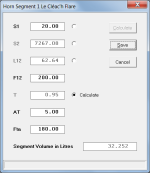
Given the desired throat cross-sectional area S1, throat entry half-angle AT, flare cutoff frequency F12 and mouth flare tangent angle Fta, the Hornresp Horn Segment Wizard can specify the resulting Le Cléac'h horn, as shown in Attachment 1.
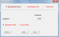
Axisymmetric, rectangular or petal horn construction dimensions can then be exported, as shown in Attachment 2.
Attachments
IIRC, the angle is only used to calculate the initial starting wave front area.I'm using a version of the spreadsheet that was shared some years ago in this thread. I noticed that the comression driver exit angle can be specified and it does influence the profile calculations, however it doesn't result in the throat of the horn matching the exit angle. It seems to match the CD exit angle requires iterating the T coefficient and perhaps Fc. How is the exit angle in the spreadsheet taken into account exactly?
Dan
Directivity-wise, the matching of angles doesn't do much, but as the difference between the exit angle and horn increases, there will be an increasing amount of reflection at the interface. This will cause some response ripples.
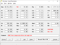
In the attached example, the first plot shows a horn with a 5cm throat adapter, having the same angle as the horn throat. The next plot shows the effect of a 8cm long adapter, which has a different angle. The most obvious effect is the bump near cutoff (due to the added length with a lower expansion rate), but you can also see the response is more uneven at high frequencies. That is due to the reflections at the interface between the adapter and the horn.
Constant throat velocity was used to remove the effect of driver parameters.
Attachments
In the power response or on-axis response? Was the horn mounted in free air, in a baffle, or sticking out from the baffle a bit? It's so long since I've used AxiDriver that I can't remember what limitations there are. If the horn was sticking out from a baffle, there would be ripples from that as well. Could you share the geometry and results?
My point was only to show that there is an effect, not the exact amount. But it could be useful to see the results from a more accurate simulation.
My point was only to show that there is an effect, not the exact amount. But it could be useful to see the results from a more accurate simulation.
Thank you everyone for that, I think I understand why the exit angle cell in the spreadsheet wasn't quite working as I expected. And thank you David McBean for the additional info on using the horn segment wizard in Hornresp. I had been using it but until now hadn't quite realized how it could be used to get the desired expansion rate and entry angle to the horn. I had been following your and Marco's contributions in the other thread on matching compression drivers to horns and now I think it all makes sense.Given the desired throat cross-sectional area S1, throat entry half-angle AT, flare cutoff frequency F12 and mouth flare tangent angle Fta, the Hornresp Horn Segment Wizard can specify the resulting Le Cléac'h horn, as shown in Attachment 1.
Axisymmetric, rectangular or petal horn construction dimensions can then be exported, as shown in Attachment 2.
So, if I understood this correctly here is how I think one can iterate to achieve a match for both the expansion rate of the throat of the compression driver and also a match between the compression driver exit angle and the horn entry angle (at least for the LeCleach horns):
- In the wizard, enter S1 and S2 based on the dimensions of the internal throat of the compression driver. Start with a desired T and F12 and have the wizard calculate L12.
- Hold T fixed and adjust F12 until L12 matches the internal dimension of the compression driver.
- Now set S1 to the exit area of the compression driver and calculate the horn with the current values for T and F12. If you're lucky the entry angle for the new horn will be close to the exit angle of the compression driver.
- If it isn't, go back and repeat step 1 with a larger or smaller value for T and find a new F12. Hopefully the new horn then arrives at a better match for the entry angle.
Dan
here is how I think one can iterate to achieve a match for both the expansion rate of the throat of the compression driver and also a match between the compression driver exit angle and the horn entry angle
I would be happy to be proven wrong, but I suspect that one could manually iterate "forever" and not achieve the desired perfect match
.The compression driver would most likely have a conical or possibly an exponential exit duct expansion rate, and could never be an exact match to a Le Cléac'h horn profile, no matter what values are chosen for T and F12.
I would simply use the Horn Segment Wizard calculation option setting that I showed in the first attachment of Post #1812 and make the entry angle of the horn the same as the exit angle of the compression driver, checking that for the desired horn flare cutoff frequency the calculated value of T is no greater than 1. (For a fixed S1 and AT the value of T can be lowered if necessary by increasing F12).
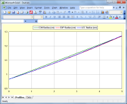
You could check this by comparing the profile of a short (say 5cm) 300Hz exponential segment with a 1" exit diameter to the equivalent (T=1) Le Cléac'h horn.
Assuming that the compression driver duct has the following dimensions:
S1 = 2.93 cm^2
S2 = 5.07 cm^2
L12 = 5.00 cm
If L12 = Exp then:
F12 = 300.21 Hz
Fta = 3.98 deg
If L12 = Con then:
Fta = 3.49 deg
If L12 = Lec and T = 1 then:
F12 = 302.00 Hz
Fta = 4.02 deg
The three profiles are compared in the attachment.
Attachments
- Home
- Loudspeakers
- Multi-Way
- Jean Michel on LeCleac'h horns