A WMTMW will sound better as it better approximates a point source and has modest baffle ripples. That's why the industry experts design them.
For a happy life, build speakers your wife and teens will want to show off to their friends, both for cool sound and cool looks.
W= Lambda TD15S in ported box
M =Lambda TD 6.5 new 6.5" speaker in sealed box
T= RAAL or NeoPro5 ribbon
LR4 xovers at 100 and 2.5K
Should be flat from 25Hz-25Khz at 96db/watt with 2db baffle step compensation
Attachments

OK gents,
I posted a simplified image of what I was thinking on this matter, thus only 4 W and 4 M per speaker.
But if I decide to go with i.e. 8 W, 4 M and maybe 1, 2 or even 4 T I'll not be able to place all these drivers vertically with the T(s) centered at ears height; thus the idea to place all the drivers on circles surrounding one or more T placed at ears height.
My question is: does such a configuration affect the stereo image and sound stages in a stereo listening?
Without doubt crazyhub's layout aproximate a point source much closer than a WMTMW layout.
Not that a point source necessarily is something to strive for though.
Crazyhub, can you tell more about your idea such as driver size, open baffle or boxed. Free standing or close to wall, maybe in wall and so on.
/Peter
Not that a point source necessarily is something to strive for though.
Crazyhub, can you tell more about your idea such as driver size, open baffle or boxed. Free standing or close to wall, maybe in wall and so on.
/Peter
I think Pan has the right idea, what size drivers are you considering? That is, the rated size and the outside dimension.
Are we looking at 15" woofers with 6" midbass speakers, or are we looking at 6" woofers with 2" or 3" dome midrange? Or perhaps, 3" or 4" cone midrange?
While my level of knowledge only allows me to speak at the conceptual stage, I wonder why a square cluster of midrange and not a vertical array?
Also, could you make a tighter cluster of midrange by putting the tweeter above the cluster and moving the midrange closer together? That would make the midrange more of a points source of sound. I think if you calculate the distance between centers on the midrange, that should help you determine at what frequency problems are likely to occur. If you crossovers keep you out of or away from the problem frequency, it should work OK.
Though I realize that you've presented only a rough sketch, I would think a tighter cluster all around would be better. Move the Woofers closer together (side-to-side), make the midrange cluster tighter, and place the tweeter above the mid-cluster.
Just a few thoughts.
steve/bluewizard
crazyhub said:
Shift the drivers around a bit to reduce the driver symmetry and vary the CTC spacing. Lobing will be an issue with this many drivers in a design no matter what. Do you REALLY need that much displacement?
Thanks guys for your inputs and links.
I should have named this thread "circle array"...
I opened it only in a theorical perspective.
I have now a good idea of how I should have asked using a simplier example:
Don't take into consideration baffle step losses or any diffraction issues.
Assuming a circle of say six 5" midwoofers surrounding one tweeter; the tweeter is at ears height.
Suppose the frames and placement of these drivers give the following building possibility: the distance from the tweeter center to each midwoofer center allows to avoid (or at least strongly minimize) any lobing problems at x-over frequency; at this point I don't see any occuring problem, notably because distance of each of the midwoofers to my ear is strictly equal, OK?
Now I decide to go to a 3-way set-up making a highpass filter for the mids and place say eight 10" woofers on a circle surounding the 6 mids. As previously stated, suppose that the distance from each woofer center to its mid neighbor center permits to avoid or minimize lobing problems at x-over frequency.
Here I guess this set-up should work even more properly than a vertically centered line array notably because the distance between EACH woofer to EACH mid is minimized, no?
In an array like that the acoustic centers of the three sections coincide... there will not be "lobing" at the crossover from the center to center offset. Each of the sections will however have narrowing directivity at HF as they are flat radiators. You will have to choose crossover points accordingly to avoid holes in the off-axis and power responses.
For example, if you had six 5" mids surrounding a tweeter, that would have the directivity of a 15" or 18" woofer, meaning you would have to cross below 1k to avoid a hole off-axis (and be very output limited) or if you crossed at a comfortable point for the tweet you'd have a 1-2 octave hole off-axis and in the power response.
As that example hopefully illustrates, you'll have to use smaller midranges that what you normally would in order to make this work. In the end, if you demand reasonably behaved directivity you end up with about the same midrange surface area as a similarly performing MT. There are some advantages though. The array smaller drivers avoids the lobing at the crossover because the acoustic centers coincide. The four smaller drivers will probably be a little more efficient than one big one, and may have more thermal mass in the voice coils resulting in lower power compression. The downside is cost... the array will probably cost more.
When I was looking at this I was considering doing a 3/4" or 1" dome tweeter surrounded by four 2" dome mids (Daytons). Four of the 2" dome mids would be 96 dB 1w/1m, have four 2" voice coils to dissipate heat, and would be very clean through the region I'd be using them. The downside is that they had big motors so I could not space them, even after trimming the faceplates, tight enough to push the crossover high enough. For the time being I abandoned the idea (I use a waveguide+cd), but I might have to look into it again.
I'd probably look at something more like a:
M W
M
M W
T
M W
M
M W
otherwise you'd have very limited directivity as Rybaudio has pointed out. But if I was, I'd probably be going with 5 mids, as the tweeter should be made a small as possible. It would still be roughly an 11" mid for directivity...
The other option for that format would be to have the tweeter at the centre of a horn (a la Unity), midranges around it and possibly the woofers around that. I don't have the knowledge to comment on that design, but I believe that some of the directivity issues are solved by this.
M W
M
M W
T
M W
M
M W
otherwise you'd have very limited directivity as Rybaudio has pointed out. But if I was, I'd probably be going with 5 mids, as the tweeter should be made a small as possible. It would still be roughly an 11" mid for directivity...
The other option for that format would be to have the tweeter at the centre of a horn (a la Unity), midranges around it and possibly the woofers around that. I don't have the knowledge to comment on that design, but I believe that some of the directivity issues are solved by this.
this layout was discussed earlier
This layout was discussed earlier in a thread where I looked for input to what speakers to build!
You can read about it here:
http://www.diyaudio.com/forums/showthread.php?s=&threadid=101908&highlight=
a few posts down.
The concept was not completely rejected, as long as the driver sizes was kept small. I however went with a line array instead...
OK,
but is it sure that the directivity of such a "circle array" can be regarded (even approximated) as a driver alone of same SD?
After all multiple small pistons don't possess the same behaviour than a biggest one thus not the same directivity...
Am I wrong with this statement?
but is it sure that the directivity of such a "circle array" can be regarded (even approximated) as a driver alone of same SD?
After all multiple small pistons don't possess the same behaviour than a biggest one thus not the same directivity...
Am I wrong with this statement?
crazyhub said:but is it sure that the directivity of such a "circle array" can be regarded (even approximated) as a driver alone of same SD?
That statement is clearly false, because it implies that the arrangement of the smaller drivers doesn't matter (only the net Sd). However, for a tightly packed array, a driver of similar "radius" is a decent approximation. I never use that though because it is straightforward to model the directivity of the array directly. For example, for a 4 driver square array:
First off, a piston's directivity function is:
R(x) = 2*J_1(k*a*sin(x)) / (k*a*sin(x))
J_1: Bessel function of first kind and first order
x: angle off-axis
k: wavenumber (w/c where w is angular frequency and c the speed of sound)
a: piston radius
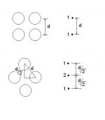
For an array of sources, all of the same directivity, the total directivity of the system is the directivity of the sources multiplied by the directivity of the array. The directivity of an array of say 4 sources in the two main dimensions has a simple expression. The geometry in the attached picture shows how to think about this. Putting this together, the directivity of the system in the two main dimensions is:
R(x) = 2*J_1(k*a*sin(x)) / (k*a*sin(x)) * |1 + e^(i*k*d*sin(x))| /2
and
R(x) = 2*J_1(k*a*sin(x)) / (k*a*sin(x)) * |1 + 2*e^(i*k*d/sqrt(2)*sin(x)) + e^(i*k*d*2/sqrt(2)*sin(x))| /4
The first factor is the directivity of the piston, and the second factor the directivity of the array. The symbol | | means complex modulus, and we need to divide by 2 and 4 respectively so that on-axis we get 1.
How you take it from here is up to you, but what I do is make a function in matlab that has as inputs the piston radius (a), center-center separation (d), and frequency (w/2pi), and displays the corresponding polar plot for both axes.
Attachments
Possibly you could look into Bessel arrays (not much info, though) as a way of using multiple drivers in 'close' formation (not necessarily circular) to simulate a point-source?crazyhub said:maghen, thanks for the link...bjornos sims told me I was wrong in my idea that circle arrays do pull lobing frequencies up; indeed it's the contrary...even if I don't physically understand why
")
crazyhub said:bjornos sims told me I was wrong in my idea that circle arrays do pull lobing frequencies up; indeed it's the contrary...even if I don't physically understand why
Think about why a piston has directivity- because when you go off-axis, you are a different distance from the various points on the cone, making the waves coming from those points not add perfectly. A circle array has more radiating area away from the center when compared to a piston, hence this effect is worse (more directivity at the same frequency or lower frequency for a given directivity).
- Status
- This old topic is closed. If you want to reopen this topic, contact a moderator using the "Report Post" button.
- Home
- Loudspeakers
- Multi-Way
- WWMMTMMWW drivers surrounding the T