I think I read the patent a few months ago.
The way *I* understood it , it is a lot of synergy horns lined up under each other. Then by selectively delaying/advancing the signal of the drivers further to the mouth, it acts as if the angle of the synergy horn is wider/smaller than it is. (Off course the crossover range of said drivers also must be adapted to the altered entry point in the virtual horn.)
Basically this is a synergy horn with selectable beamwidth and therefore efficiency. (You can throw lots of efficient SPL in a narrow beam to the end of the venue, and as you get lower/closer to the front stage, you can widen the beam, giving less efficiency/SPL to the people nearby. All from an apparent point source.
I can have understood this wrong, but given my knowledge of line arrays and the pros and cons of different techniques for even coverage, it makes sense to me.
The drivers must be all separately amplified and DSP-ed to pull this one off, or if Danley can get this with a passive crossover I sure would like to see that!
musgofasa said:I could see doing it with passive network as the drivers are all going to be customized to the application. One thing is for certain. It should have a hefty price tag. I would like to hear it in use though. Pretty design.
Big too and i like Big! lol
Hm, still assuming I am correct, then how would someone make a passive crossover with an adjustable variable delay for each driver?
Only by going active, I think.
I expected the outer horn to be paved with mostly identical drivers, but seeing this picture, I think I should search for and reread the patent ...
Ah I didn't actually notice that comment before. I went back and read some of TD's site. It could be a really complex delay after all. I sure am glad I don't do pro sound sometimes lol. I would need way too many definitions of "line array performance" and "front to back dispersion" etc. I have never tried to work with such a large area as a concert venue and I know nothing about that sort of thing lol. I was only thinking of Danley's custom drivers. He wouldn't need an active crossover just for frequency corrections, but to get all the details described, I think you might be right. Don't forget, I am frequently wrong lol.
"Shaded Amplitude Lens"??? Interesting.
Take care,
Robert
"Shaded Amplitude Lens"??? Interesting.
Take care,
Robert
Hi Patrick, Earl, All
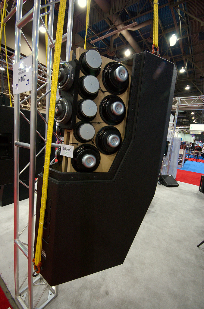
Ah, GH-60 at some trade show .
The principal behind the GH-60 may be harder to convey in writing .
It uses some more recent inventions, the Paraline lens and Shaded Amplitude Lens (pat pend)
With any explanation of a system which has a “big picture” absorbed in “parallel” one much explain in series. I will explain a couple key aspects needed to see the system.
In a piston, ribbon or other homogeneous source which is large enough to effect / produce a radiation pattern, one finds that the degree of this is directly related to the sources size relative to the wavelength.
Once a source is acoustically small enough to produce spherical radiation, it has become a classical point source with no directivity, making it smaller has no further effect on pattern..
Line sources are very popular, when compared side by side with “prior art” concert loudspeakers, one often finds the Line array to be subjectively superior.
Part of the reason is that essentially no consideration was ever given to making the multiple ranges in each box actually combine acoustically.
Old style concert loudspeakers arrays had so much self interference that even one box, (in addition to its other issues) doesn’t normally sound good like hifi and the more you have in one stack, the worse it gets.
In practice, as the real line sources are to varying degrees NOT a homogeneous source top to bottom, they do have the self-interference of physically separate sources as well as the more desirable effect. An exception, I would like to think and based on subjective impressions so far is the VTC array which uses the geometry I use in the Synergy horns and the Paraline which produces a homogeneous wavefront entering the horn.
A typical Line array’s driver arrangement confine the self-inference to mostly one plane, up and down and in that plane it is harder to move around and “hear” than in the horizontal plane.
Also, when the line is “long enough”, it’s sound pressure vs distance can approach half the roll off rate of a point source, a point that is strongly advertised but less often measured.
A curious feature; when one makes a real line source, say 10 or 20 feet long and it is hanging in the air, as normally used, one finds that at low frequencies, it is too small to have any real effect on directivity, it is a point source.
The low frequency spectrum is radiated and falls off as a point source would.
Higher up, one finds the vertical pattern narrows. Much higher up in frequency when the length of the line is many wavelengths long, the system finally begins to radiate the classical “cylindrical” wavefront of a line source.
To reduce the magnitude of the “size / frequency effect”, the line is usually curved physically, electrically or both so that it behaves more like a point source. Also, it is common to shade the frequency response of the elements of the line source, also make it act more like an constant directivity source. (more like an astigmatic point source than classic cylindrical)
THE unmentionable flaw of the typical line array is that when one has a physical configuration which is acoustically large enough to produce a cylindrical radiation and have the desired reduced fall off vs distance, one is also in the zone where what you measure is a direct function of the geometry (the source, the mic position and distance).
In other words, the frequency response ALSO changes with distance, requiring the use of aiming programs, which show nice colors representing an ideal world result. Ever see a frequency response curve for any of these?
Ok, file this for now.
A plain simple conical horn, driven at the apex at an acoustically small dimension, by an acoustically small source, radiates essentially a spherical segment, with the same wave curvature the source would radiate if the horn weren’t present, except confined to a much smaller angle instead of a full sphere.
This shape horn maintains more or less a constant radiation angle down to a frequency where the mouth size and wall angle are no longer able to define this.
Don Keele’s thumb rule approximates this well, as does his description of the narrowing, which happens just above the loss frequency. The solution for the latter is to make the last third of the horn a larger angle.
File this away;
I have tried through out all the work on these multi-way horns, to make the drivers for the different frequency ranges and horn geometry, have a relationship that allows them to add together as coherently as possible to act like one driver.
For the commercial sound area, it is normal to have several boxes side by side in order to reach a desired angular coverage.
On page 7 of the white paper thingy, you can get the crude marketing idea for the geometry one needs to array several horns. Theory requires the acoustic origins for adjacent boxes to be as close as possible to the same place and the distance between horn walls as small as possible. In practice, the larger the mouth is (the lower its pattern loss frequency), the thicker the gap can be between horn walls can be.
Now, if one uses two SH-50’s arrayed, one finds that per Don Keele’s thumb rule, that the pattern loss frequency is lower. One has increased the total angle to 100 degrees AND one has increased the mouth width to 56 inches, both lower that pattern loss F.
File this away;
What is the point of all this anyway?
From the perspective of the loudspeaker over a stage with audience, one finds that the back row is say 4-8 or more times the distance to the front row.
A constant directivity point source has no inherent change in frequency response VS distance but does have a greater fall off with distance than a line array.
In the olden days, it was common to address this problem with a large narrow long throw horn aimed at the back row and a medium and short throw horns positioned below to cover the closer seats. Unfortunately, these systems also had significant source-to-source interference and certainly weren’t broad band or hifi sounding but “that” idea is the goal I had.
The Shaded amplitude lens is a way to make a point source but have it project more strongly on one angle than another.
The idea here is that you plot out the distance and down angle from the speaker at a number of points from the front to back and then compute the amplitude distribution vs Vertical angle that is needed from the source to achieve a constant SPL or “perfect line source” fall off or what ever where 'de peeps are.
How?;
Imagine you sliced up an imaginary 50 by 50 horn and had 5 identical horns, each one with 10 degree(h) by 50 degree (v) walls.
The mouth size and wall angle define the pattern loss frequency, which because of the narrow angle and small width is a high frequency.
Now, I found a funny thing, the crux of this.
If one took the 5 identical 10 degree straight walled conic horns and arrayed them like I described back into a 50 by 50 horn, one finds that up to some very high frequency, they sum into one horn of the total shape and angle.
If one made the center horn full level and made the two adjacent ones say –3Db and the next two –9dB, then one finds a narrower beam can be made than the normal thumb rule would allow given the frequency and dimension.
I think this works because in a normal horn, the transition (that the thumb rule describes) at the edge as the wave leaves the mouth, goes from feeling the full acoustic mirror pressure of the horn wall, to “nothing” when the wall stops. In the amplitude-shaded horn, instead of that abrupt change, the pressure is gradually reduced as one gets to the edges.
In the GH60, all this Shading happens in the Vertical pattern.
I divided up the uniform acoustic pressure from a full range source at acoustic dimensions which allowed it to be bent and then redirected “bent” those portions to a different direction to produce the shading I needed.
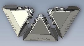
The GH-60 box is hung plumb (up an down) up off the ground, looking down, it covers a 60 degree wide pie slice of audience. Pix1
From the side, the coverage begins 5 degrees down from horizontal, projects most strongly at about 15-20 degrees down and coverage ends 10 degrees from straight down.
The amplitude was shaded to produce the SPL fall off vs distance of the theory perfect line array of –3dB per doubling of distance on a flat floor and near constant SPL vs distance on a raked floor.
This is new product, there aren’t a lot of measurements on it yet and has been a pain to figure out. Actually I had asked Earl a while back if he could give me a hand figuring out part of this but I ran out of time on that too.
One measurement / test that will be posted was two of these compared to an eight-box SLS ribbon based line array with full processing and aimware etc.
Here with both systems suspended in the air, the responses were measured at a bunch of distances out to the end of the pattern of the GH-60 (I think they did it to 150 feet) .
The two GH-60’s ( a passive box here, using one amplifier channel) produced a smoother response everywhere, much less change in frequency response over the distance and less fall off in SPL than the line array.
Subjectively, every one was surprised to find the Line array reached limiting sooner and was never as clear and crisp.
Anyway, top be honest, these shaded amplitude things (the understanding / design of them) are a work in progress, this box works pretty good for a first product and does something useful for large spaces.
So far as the low end, with the area being large and normally two or three or even more boxes used, conventional horn loading of the black drivers worked well enough.
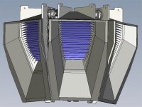
I have attached a drawing from the front side.
Each vane you see represents a step of 1.5, 2 or 3 dB with down (the front row) being the lowest level. Pix2
Best,
Tom Danley
Ah, GH-60 at some trade show .
The principal behind the GH-60 may be harder to convey in writing .
It uses some more recent inventions, the Paraline lens and Shaded Amplitude Lens (pat pend)
With any explanation of a system which has a “big picture” absorbed in “parallel” one much explain in series. I will explain a couple key aspects needed to see the system.
In a piston, ribbon or other homogeneous source which is large enough to effect / produce a radiation pattern, one finds that the degree of this is directly related to the sources size relative to the wavelength.
Once a source is acoustically small enough to produce spherical radiation, it has become a classical point source with no directivity, making it smaller has no further effect on pattern..
Line sources are very popular, when compared side by side with “prior art” concert loudspeakers, one often finds the Line array to be subjectively superior.
Part of the reason is that essentially no consideration was ever given to making the multiple ranges in each box actually combine acoustically.
Old style concert loudspeakers arrays had so much self interference that even one box, (in addition to its other issues) doesn’t normally sound good like hifi and the more you have in one stack, the worse it gets.
In practice, as the real line sources are to varying degrees NOT a homogeneous source top to bottom, they do have the self-interference of physically separate sources as well as the more desirable effect. An exception, I would like to think and based on subjective impressions so far is the VTC array which uses the geometry I use in the Synergy horns and the Paraline which produces a homogeneous wavefront entering the horn.
A typical Line array’s driver arrangement confine the self-inference to mostly one plane, up and down and in that plane it is harder to move around and “hear” than in the horizontal plane.
Also, when the line is “long enough”, it’s sound pressure vs distance can approach half the roll off rate of a point source, a point that is strongly advertised but less often measured.
A curious feature; when one makes a real line source, say 10 or 20 feet long and it is hanging in the air, as normally used, one finds that at low frequencies, it is too small to have any real effect on directivity, it is a point source.
The low frequency spectrum is radiated and falls off as a point source would.
Higher up, one finds the vertical pattern narrows. Much higher up in frequency when the length of the line is many wavelengths long, the system finally begins to radiate the classical “cylindrical” wavefront of a line source.
To reduce the magnitude of the “size / frequency effect”, the line is usually curved physically, electrically or both so that it behaves more like a point source. Also, it is common to shade the frequency response of the elements of the line source, also make it act more like an constant directivity source. (more like an astigmatic point source than classic cylindrical)
THE unmentionable flaw of the typical line array is that when one has a physical configuration which is acoustically large enough to produce a cylindrical radiation and have the desired reduced fall off vs distance, one is also in the zone where what you measure is a direct function of the geometry (the source, the mic position and distance).
In other words, the frequency response ALSO changes with distance, requiring the use of aiming programs, which show nice colors representing an ideal world result. Ever see a frequency response curve for any of these?
Ok, file this for now.
A plain simple conical horn, driven at the apex at an acoustically small dimension, by an acoustically small source, radiates essentially a spherical segment, with the same wave curvature the source would radiate if the horn weren’t present, except confined to a much smaller angle instead of a full sphere.
This shape horn maintains more or less a constant radiation angle down to a frequency where the mouth size and wall angle are no longer able to define this.
Don Keele’s thumb rule approximates this well, as does his description of the narrowing, which happens just above the loss frequency. The solution for the latter is to make the last third of the horn a larger angle.
File this away;
I have tried through out all the work on these multi-way horns, to make the drivers for the different frequency ranges and horn geometry, have a relationship that allows them to add together as coherently as possible to act like one driver.
For the commercial sound area, it is normal to have several boxes side by side in order to reach a desired angular coverage.
On page 7 of the white paper thingy, you can get the crude marketing idea for the geometry one needs to array several horns. Theory requires the acoustic origins for adjacent boxes to be as close as possible to the same place and the distance between horn walls as small as possible. In practice, the larger the mouth is (the lower its pattern loss frequency), the thicker the gap can be between horn walls can be.
Now, if one uses two SH-50’s arrayed, one finds that per Don Keele’s thumb rule, that the pattern loss frequency is lower. One has increased the total angle to 100 degrees AND one has increased the mouth width to 56 inches, both lower that pattern loss F.
File this away;
What is the point of all this anyway?
From the perspective of the loudspeaker over a stage with audience, one finds that the back row is say 4-8 or more times the distance to the front row.
A constant directivity point source has no inherent change in frequency response VS distance but does have a greater fall off with distance than a line array.
In the olden days, it was common to address this problem with a large narrow long throw horn aimed at the back row and a medium and short throw horns positioned below to cover the closer seats. Unfortunately, these systems also had significant source-to-source interference and certainly weren’t broad band or hifi sounding but “that” idea is the goal I had.
The Shaded amplitude lens is a way to make a point source but have it project more strongly on one angle than another.
The idea here is that you plot out the distance and down angle from the speaker at a number of points from the front to back and then compute the amplitude distribution vs Vertical angle that is needed from the source to achieve a constant SPL or “perfect line source” fall off or what ever where 'de peeps are.
How?;
Imagine you sliced up an imaginary 50 by 50 horn and had 5 identical horns, each one with 10 degree(h) by 50 degree (v) walls.
The mouth size and wall angle define the pattern loss frequency, which because of the narrow angle and small width is a high frequency.
Now, I found a funny thing, the crux of this.
If one took the 5 identical 10 degree straight walled conic horns and arrayed them like I described back into a 50 by 50 horn, one finds that up to some very high frequency, they sum into one horn of the total shape and angle.
If one made the center horn full level and made the two adjacent ones say –3Db and the next two –9dB, then one finds a narrower beam can be made than the normal thumb rule would allow given the frequency and dimension.
I think this works because in a normal horn, the transition (that the thumb rule describes) at the edge as the wave leaves the mouth, goes from feeling the full acoustic mirror pressure of the horn wall, to “nothing” when the wall stops. In the amplitude-shaded horn, instead of that abrupt change, the pressure is gradually reduced as one gets to the edges.
In the GH60, all this Shading happens in the Vertical pattern.
I divided up the uniform acoustic pressure from a full range source at acoustic dimensions which allowed it to be bent and then redirected “bent” those portions to a different direction to produce the shading I needed.
The GH-60 box is hung plumb (up an down) up off the ground, looking down, it covers a 60 degree wide pie slice of audience. Pix1
From the side, the coverage begins 5 degrees down from horizontal, projects most strongly at about 15-20 degrees down and coverage ends 10 degrees from straight down.
The amplitude was shaded to produce the SPL fall off vs distance of the theory perfect line array of –3dB per doubling of distance on a flat floor and near constant SPL vs distance on a raked floor.
This is new product, there aren’t a lot of measurements on it yet and has been a pain to figure out. Actually I had asked Earl a while back if he could give me a hand figuring out part of this but I ran out of time on that too.
One measurement / test that will be posted was two of these compared to an eight-box SLS ribbon based line array with full processing and aimware etc.
Here with both systems suspended in the air, the responses were measured at a bunch of distances out to the end of the pattern of the GH-60 (I think they did it to 150 feet) .
The two GH-60’s ( a passive box here, using one amplifier channel) produced a smoother response everywhere, much less change in frequency response over the distance and less fall off in SPL than the line array.
Subjectively, every one was surprised to find the Line array reached limiting sooner and was never as clear and crisp.
Anyway, top be honest, these shaded amplitude things (the understanding / design of them) are a work in progress, this box works pretty good for a first product and does something useful for large spaces.
So far as the low end, with the area being large and normally two or three or even more boxes used, conventional horn loading of the black drivers worked well enough.
I have attached a drawing from the front side.
Each vane you see represents a step of 1.5, 2 or 3 dB with down (the front row) being the lowest level. Pix2
Best,
Tom Danley
Attachments
Tom Danley said:The idea here is that you plot out the distance and down angle from the speaker at a number of points from the front to back and then compute the amplitude distribution vs Vertical angle that is needed from the source to achieve a constant SPL or “perfect line source” fall off or what ever where 'de peeps are.
Best,
Tom Danley
Hi Tom
There is s imple way to do this, just look at the Transform theory for a line source. Its basically just the Fourier transform of the desired polar plot. This method works at all frequencies while the one you describe is limited to HF where line of sight approximations hold.
In practice, the idea of a "J" array also does what you describe.
I did some line array designs for a guy in Brazil and they are very popular down there but there are so many on the market here that he'd get lost in the crowd.
I am not convinced that the line array is the end all design for high power apps, but it solves a few problems. I think that some updated work on the old "cluster" concept might work better, but that's just a guess. As you said, in the past these were done with no consideration for merging the acoustics of the different driver ranges together. That was their failing. But things don't have to be done wrong, they could be done right and maybe this approach would have some merits.
Wow,
That actually explained why the best sounding concert I ever went to sounded so much better than a lot of others.
While I may never gain the experience to understand a lot of the acoustics of larger venues (boy what I wouldn't give to be in the business though) it is cool to be able to look back at certain shows I have been to and remember how they were set up and think "that's how they did that" lol
Thanks Tom
Robert
Hi Tom,
Thanks for explaining the principles of your product.
I'm happy to see I was right about the different "throw" Vs vertical angle, but I have a few questions about the directivity of the low end.
You say conventional horn loading of the lower freq works well enough when clustered, but how does it behave in a single Genesis Horn? I can imagine that you lose directivity the more you lower the frequency, so for a single GH-60 some kind of boost would be required similar like with a traditional line array, correct?
My initial misunderstanding of using multiple delayed drivers to adjust the throw got me thinking how much of a "point source" a certain freq range is inside a synergy horn and how to use this to direct more bass to the front.
Let me explain this: it is possible to put a number of subwoofers in a line and apply increasing delay to them so they sum on-axis and to the front of the line. Done that way, one can reduce the back spill and direct the bass (cardioid???) to the front of the stage.
Suppose one would try the same by adding extra woofers to the mouth of a synergy/genesis horn to create a second bass-only point source at the mouth. The extra woofers would have to be crossed over lower than the woofers closer to the throat, but the extra source could be used to create cardioid bass to extend the directivity of the lower freq past what the mouth size dictates.
So my questions are if it is possible to create 2 or more point source equivalents inside the same horn and if you have considered this to further direct the lower bass?
If you have decided to not pursue it, what was the physical/economical reason?
eager to learn,
Joris
it is possible to put a number of subwoofers in a line and apply increasing delay to them so they sum on-axis and to the front of the line.
Bob McCarthy and Rog Mogale provide explanations and details on using delay to shape dispersion of bass.
This is Mogale work:
http://www.voidaudio.com/pdf/bass guide.pdf
There is actually a rather simple way to do the line array problem because the polar response is the Fourier Transform of the line array velocity response. Delay is just a set of complex coefficients, Shading is amplitude. Plug in the desired polar pattern and the inverse transform tells you what the amplitude and delay of each element needs to be.
If you want to take the drivers inherent polar patern into consideration then the final response is just the product of the individual drivers polar response and the line response for point sources. Doing the Fourier Transform on a odd numbered array means that you have to do it by brute force, but thats not very hard, its just not as fast as say the FFT.
If you want to take the drivers inherent polar patern into consideration then the final response is just the product of the individual drivers polar response and the line response for point sources. Doing the Fourier Transform on a odd numbered array means that you have to do it by brute force, but thats not very hard, its just not as fast as say the FFT.
Is it really that complicated?
Not trying to stir any pots (please don't think that) but I have a thought that the actual design origin wasn't that much calculation.
If it really is, hats off to both of you for the knowledge to actually foresee a result from something so complex.
Maybe I should explain why I say that. I don't want anyone to think I am being instigative here. I have found over the years that reverse engineering answers a lot of questions after the "mistake" caused the new invention. I have read a LOT of Gedlee's posts recently and tend heavily to agree with assessments of moving things around, taking measurements, listening, and then making adjustments to achieve the desired effect. (I think I am referring to sub placement, but I read a lot) and this tends to be how I approach room and speaker design when I build systems for customers. (I have been out of the biz too long). There are certain experiences that lead us to go in a direction when designing something new, but the math usually ends with the knowns and the design becomes a bit of hit or miss for most as we test something, throw it out, test something else, take the best of what we have and try to improve from there.
Do you guys really sit down with a 3d drawing of the space or the design and then calculate the ideals that you want to achieve?
Probably completely off topic, but I find it very interesting to ask the "best of the best" about their methodology. If you guys are really that much better than me at predictions, I am really admiring your dedication to research and would love the opportunity to learn from either or both of you.
I see a lot of posts like this get flamed for arrogance so please believe I am being humble here and would simply like to know how much of your designs are build ups from something else and how much are done on the drawing board before ever going to any sort of test production.
Thanks,
Robert
- Status
- This old topic is closed. If you want to reopen this topic, contact a moderator using the "Report Post" button.
- Home
- Loudspeakers
- Multi-Way
- I Don't Understand.