Any thoughts on this concept? Any suggestions on bass drivers for the 3-way Pro9 cabinets?
Kef B139. But if you have those there are better lines. When building a TL, choose the driver and then design the line. Few designs that pre-date the release of King/Augspurger modeling software are optimum.
dave
Hi Everyone,
Just reading through this thread. I have my father has finally handed over his IMF RSPM Mk IV speakers and phase linear amp.
I would like to also like to attempt a modern version of these beautiful speakers.
are there any plans still floating around the net I can get my hands on?
Also where is the n00bs guide to building TL speakers?
")
Just reading through this thread. I have my father has finally handed over his IMF RSPM Mk IV speakers and phase linear amp.
I would like to also like to attempt a modern version of these beautiful speakers.
are there any plans still floating around the net I can get my hands on?
Also where is the n00bs guide to building TL speakers?
Well, for a start, don't try building them like IMF, unless you are willing to use drivers that have very similar Fs, Q and Vas properties. Those lines worked OK because they suited the LF driver (usually KEF 139 variations). But people will insist on trying to design a physically similar line for drivers that are completely different -and, astonishingly enough, the results suck like an asthmatic baboon up a baobab tree.
Quarter Wavelength Loudspeaker Design
Transmission Line Theory
http://www.quarter-wave.com/TLs/TL_Anatomy.pdf
http://www.quarter-wave.com/TLs/Alignment_Tables.pdf
http://www.quarter-wave.com/TLs/Alignment_Tables_Calculator_3_3_09.xls
Note: Martin's alignment tables assume the line is tuned to Fs, which some people miss on first reading. These are not the only possible alignment, just one, albeit a reasonable one, and the tables do provide you with a very good starting point for other types.
This is an alternative alignment:
http://diyaudioprojects.com/Technical/Papers/Loudspeakers-on-Damped-Pipes.pdf
A handful of points (which you'll find in the above links, either directly or indirectly):
1/ Line cross sectional area (& ultimately the volume of the line) has zero direct connection to driver Sd. Martin (King -of Quarter-wave.com) sometimes uses multiples of Sd as a convenient way of expressing area, but it is no more than that, and with hindsight I suspect he wishes he had not done so as it helped perpetuate the myth that Sd and line CSA have a direct connection.
2/ The speed of sound does not significantly decrease through a fibrous tangle (aka stuffing)
3/ There is nothing magical about long hair wool, or any other damping material for that matter. They all possess somewhat different damping characteristics, but there is no mystery about that, and the differences are not generally night & day.
4/ The critical driver characteristics for a TL of any kind (TL has unfortunately become a catch-all term that is used to refer to all kinds of pipes ranging from maximally flat impedance designs, which are almost completely unresonant & have almost no output from the terminus, to highly resonant designs) are Qt, Fs and Vas, just as they are for any other kind of vented alignment.
5/ Pipe tuning frequency is a function of both axial length and taper. Leaving aside end correction for a moment, the assumption of ((SoS / Fp) / 4) only works for untapered pipes (where SoS = speed of sound & Fp = pipe tuning frequency). An expanding pipe (conical horn) will have a higher Fp for the same axial length, a narrowing pipe will have a lower Fp for the same axial length.
Last edited:
OK so where do we (those who are not going to learn HR) find the means to use the three bigs to design our latter-day offset driver TLs? Everyone around here seems to be Windows wizards but some of us don't have enough years remaining to attempt that one. Case in point: the Morel UW-1058 design in a recent thread, which according to PKitt should be happy in a tapered line that is about 3X vas. Kinda big for a 10", or is it?
Scott & i did do a classic TL in the mold of the Radford/IMF/TDLs/Last entry here: Transmission Line Speakers
I don’t think it has been all that popular, and i expect it could be improved on, possibly even just by mounting the driver son the back.
dave
I don’t think it has been all that popular, and i expect it could be improved on, possibly even just by mounting the driver son the back.
dave
OK so where do we (those who are not going to learn HR) find the means to use the three bigs to design our latter-day offset driver TLs? Everyone around here seems to be Windows wizards but some of us don't have enough years remaining to attempt that one. Case in point: the Morel UW-1058 design in a recent thread, which according to PKitt should be happy in a tapered line that is about 3X vas. Kinda big for a 10", or is it?
Accidental MLTL Technique
^^^Try there. Be prepared to measure impedance and response vs frequency and trim the port. Rinse and repeat until happy.
OK so where do we (those who are not going to learn HR) find the means to use the three bigs to design our latter-day offset driver TLs? Everyone around here seems to be Windows wizards but some of us don't have enough years remaining to attempt that one. Case in point: the Morel UW-1058 design in a recent thread, which according to PKitt should be happy in a tapered line that is about 3X vas. Kinda big for a 10", or is it?
The pdf articles I provided links to above, including two separate sets of alignment tables from Martin King & George Augspurger, do not require Windows.
TLs are by nature large; like back horns they are inherently bulkier than other enclosure types & have a higher F3 for a given Fb than a typical vented box. MLTLs or other highly resonant sub-types are to a point slightly different in this regard, but since they are dissimilar to the IMF lines in question here, are better considered separately.
OK the Augspurger article does help a lot. MJK is beyond me, at least until I get a new email account that will get me into sites like his Yahoo group as well as Planet 10. Comcast is a joke, after all.
I got started in this quest trying to get my AR-4 budget to make bass like the AR-3, but not via the boomy reflex. Now the sealed box is resurgent but there was that period in the 80s and 90s when all the readily sourced woofers were designed for BR applications - big magnets, short voice coils.
I got started in this quest trying to get my AR-4 budget to make bass like the AR-3, but not via the boomy reflex. Now the sealed box is resurgent but there was that period in the 80s and 90s when all the readily sourced woofers were designed for BR applications - big magnets, short voice coils.
kef concerto
Hi there, I have a beautiful pair of KEF Concerto ( B139, B110, T27 ) that I would like to transform in a transmission line replica of IMF SACM or IMF RSPM or IMF TLS80....any way to find the correct drawings to replicate?
Any help or thought really appreciate
Thanks
Hi there, I have a beautiful pair of KEF Concerto ( B139, B110, T27 ) that I would like to transform in a transmission line replica of IMF SACM or IMF RSPM or IMF TLS80....any way to find the correct drawings to replicate?
Any help or thought really appreciate
Thanks
As said, not worth replicated the IMFs, they are dinosaurs, With modern modelers one can do a better line.
Scott and i have taken a basic alignment for the B139 and done a number of example boxes. You would be best to start there.
The weak part of the box will be the poor XO in the Concerto.
Personally i would swap an Alpair 5.2/3 for the B110/T27 and biamp, drawmatically improving the midTop, getting rid of the passive XO and reduce the inherent colouration of the B139.
Here is what has been done to date: Transmission Line Speakers
Somewhere i may still have a piece of paper with TLS80 dimensions. I may find it. Nobig loss if i don’t.
dave
Thanks for your prompt answer, well my first idea was to make a TL box for the B139 and a kind of LS3/5a for the top and biamp.
I was thinking to ask what is a "modern modellers" and where to find ( MJ King worksheet are no more available! ), but probably for the first attempt I would go with something already done like from the page you linked.
Cheers
I was thinking to ask what is a "modern modellers" and where to find ( MJ King worksheet are no more available! ), but probably for the first attempt I would go with something already done like from the page you linked.
Cheers
Thanks for your prompt answer, well my first idea was to make a TL box for the B139 and a kind of LS3/5a for the top and biamp.
Very much like the Fried M. Since the B200 SP1039 he used was not available for diy we used B139 (and dB systems XO). Bud even adoped a satilitte design i did, i just found a picture of it yesterday.
what is a "modern modellers
The Martin King modeler i consider the gold standard, but it is NLA, i rely on someone who knows it in-side-out and along with other proprietary tools spits out numbers for me to work with very rapidly.
SO tha tleaves the Transmisison Line Modeler, development has stopped, and it is a bit tricky to install. There is a thread on the forum
HornResp is well supported with the developer active on the forum, it is in version a zillion, but recently added damping modeling is often not used making it hard to evaluate sims. That is improving.
Augspurger costs money (if you can stil get it) has not had any updates in 20 years, and has limited capability.
dave
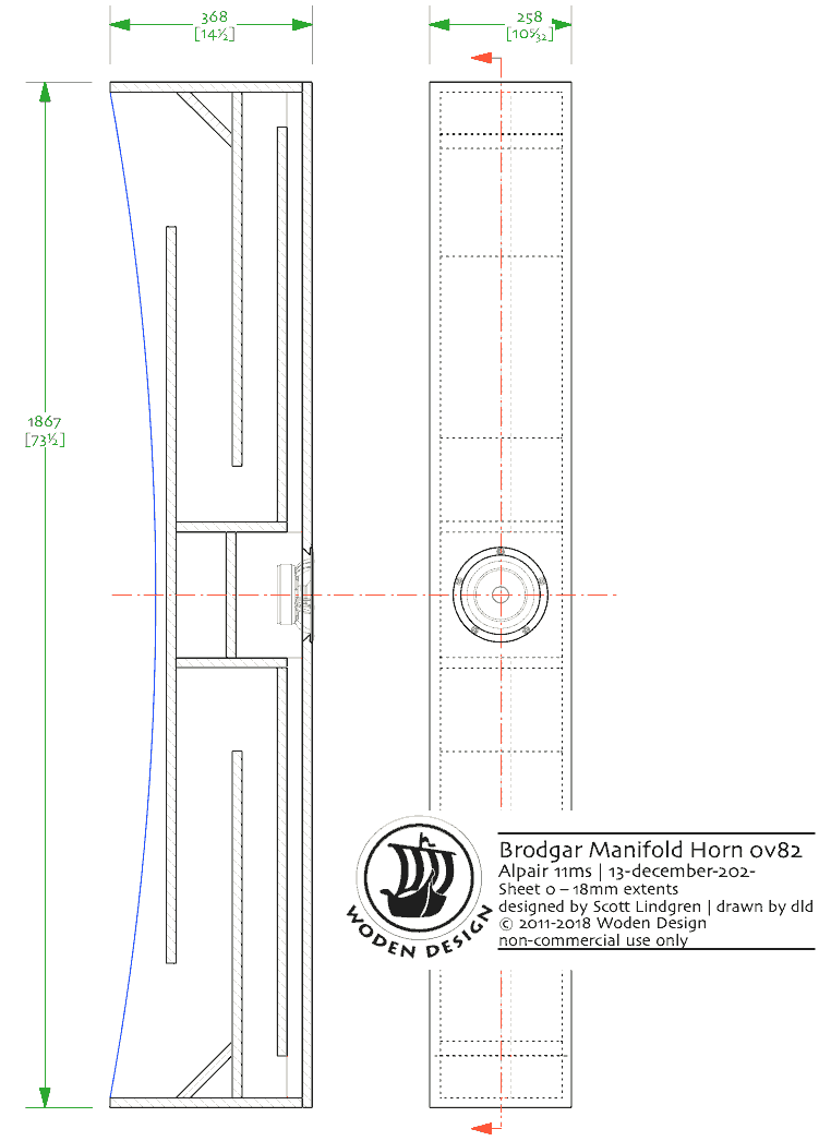
Folding a tapering pipe
It doesn’t have to be a tapered pipe. Every bend, if there is no reflector, causes an expansion in the line cross-section which acts as a low pass filter.
2 folds means 2 low passes in series.
A good example of taking advantage of this is the bit Woden horns, where there is very little damping needed in the line. In a TL thou, it often much less of an issue, given the typically much heavier acoustic damping in the box. Note that a 180° bend can have 2 expansions, a 90° fold will have 1.
dave
- Home
- Loudspeakers
- Multi-Way
- Build Replica IMF Transmission Line Speakers???