Hi all
I am reaching the end of construction of my bass enclosure, and have hit a bit of snag with the bracing.
The enclosure is made of 25mm MDF, and is 425mm x 275mm x 700mm high (19" x 11" x 28" in old measurements), with a shelf brace about 1/3 of the way from the top. All the panels ring fairly high when tapped except for the lower section of the side panels, which are 425mm wide x about 425 high. These have a fundamental frequency of around 200 Hz (by ear), which is a bit low, given that the speaker will start rolling off at around that frequency.
The plan was to fit a cross brace to break up the resonance of this panel, and I made one consisting of two all-thread 10mm rod which tightens against the enclosure wall via nuts agains two pieces of MDF. I can temporarily insert this brace by screwing the nuts so that the enclosure walls are pushed outward and the brace is in compression.
The only snag in this otherwise brilliant brace design is that it seems to have almost no effect on the frequency of resonance of the panel (tested by tapping), despite trying a number of different orientations and locations.
I calculated that the stiffness of the brace should be much higher than the wall (maybe 100x more), so I don't know why it doesn't work. The only theory that I have is that if you tap on one side, then the brace will transfer force across to the other wall, which will move in the same direction. ie when one wall moves in the other moves out.
Any thoughts on why this is happening, and maybe some other brace designs that I could try, without being permanent?
I would prefer not to add too much thickness to the wall, to preserve the volume of the enclosure. The enclosure is sealed with a volume of around 50 litres, and will be stuffed with fibreglass.
Thanks
Mick
HI, BBC research years ago showed that merely bracing the walls only shifts the ringing of panels higher in freq where it is more audible, hence their solution of thin wall enclosures heavilly damped with bitumen impregnated felt, A/LA LS3/5A, SPENDOR BC1, ROGERS, HARBETH et all....
GO TO YOUR LOCAL AUTO CRASH SUPPLY OUTLET,(YOU WILL FIND THEM IN THE YELLOW PAGES!) AND BUY SOME BITUMEN SHEET DAMPING AND STICK THAT ON THE WALLS WITH CONTACT ADHESIVE... THAT SHOULD DO THE TRICK
 CHEERS,
TJB
GO TO YOUR LOCAL AUTO CRASH SUPPLY OUTLET,(YOU WILL FIND THEM IN THE YELLOW PAGES!) AND BUY SOME BITUMEN SHEET DAMPING AND STICK THAT ON THE WALLS WITH CONTACT ADHESIVE... THAT SHOULD DO THE TRICK
CHEERS, TJB
HI, BBC research years ago showed that merely bracing the walls only shifts the ringing of panels higher in freq where it is more audible, hence their solution of thin wall enclosures heavilly damped with bitumen impregnated felt, A/LA LS3/5A, SPENDOR BC1, ROGERS, HARBETH et all....
GO TO YOUR LOCAL AUTO CRASH SUPPLY OUTLET,(YOU WILL FIND THEM IN THE YELLOW PAGES!) AND BUY SOME BITUMEN SHEET DAMPING AND STICK THAT ON THE WALLS WITH CONTACT ADHESIVE... THAT SHOULD DO THE TRICK CHEERS,
TJB
AND OH BTW, you would have been better off doing the boxes out of 16mm MDF TOO, the money you save on the cost of the MDF you could have spent on the bitumen sheets for a more inert box.... of course that is had you known the difference this would make CHEERS & CARRY ON REGARDLESS AS SID j WOULD SAY....for all is not lost yet
TJB
GO TO YOUR LOCAL AUTO CRASH SUPPLY OUTLET,(YOU WILL FIND THEM IN THE YELLOW PAGES!) AND BUY SOME BITUMEN SHEET DAMPING AND STICK THAT ON THE WALLS WITH CONTACT ADHESIVE... THAT SHOULD DO THE TRICK
CHEERS, TJB
AND OH BTW, you would have been better off doing the boxes out of 16mm MDF TOO, the money you save on the cost of the MDF you could have spent on the bitumen sheets for a more inert box.... of course that is had you known the difference this would make
CHEERS & CARRY ON REGARDLESS AS SID j WOULD SAY....for all is not lost yetTJB
Hi Qwad
Because these are bass speakers only I don't mind about shifting the resonant frequencies higher. If I can get them up around 500 Hz + then they should be largely out of harms way.
As for adding damping material now, I thought about this, and I have doubts that I will be able to damp such heavy panel at low frequencies. I don't know the theory here, but my feel is that without doing constrained layer damping (ie adding damping between another layer added to the inside of the box), just attaching damping material to one side won't make a great deal of difference.
Another shelf brace would be best, but it would be difficult to get the fibreglass filling betwen the shelf braces, and very difficult to add it in now. Maybe a couple of pieces of angle iron screwed and glued to the wall would be the best option.
I am planning to use constrained layer damping on the plinth, and I bought some 3mm wool felt yesterday that I'm going to impregnate with car underbody bitumen sealer for this purpose.
I'll probably have some left over, so I could try that on the side wall, but I'm worried about solvents in the sealer attacking the drivers.
What kind of bitumen sheet damping have you tried Qwad, and how did it work?
Thanks
Mick
qwad said:HI, BBC research years ago showed that merely bracing the walls only shifts the ringing of panels higher in freq where it is more audible, hence their solution of thin wall enclosures heavilly damped with bitumen impregnated felt, A/LA LS3/5A, SPENDOR BC1, ROGERS, HARBETH et all....
This doesn't make a whole lot of sense.
First, while bracing will increase the frequency of the resonance, moving it higher in frequency also moves it into a region where there's less acoustic energy to stimulate the resonance in the first place. And higher frequencies attenuate more rapidly in air (as well as any dampening material used inside the enclosure) than lower frequencies so there's less acoustic coupling to the panel. Also, the higher the resonance, the easier it is to damp.
Lowering the frequency places the resonance where there's not only more energy, but also where there's more efficient acoustic coupling. And trying to damp a low frequency resonance is far more difficult.
And speaking of damping resonances, that's not the same as eliminating vibration. Damping a resonance simply means to reduce subsequent ringing. Even if the panel is well-damped and not ringing, it will still flex. And a thinner panel will flex far more than a thicker panel which means that the enclosure will be far more lossy in the bass region.
And moving it to a lower frequency where it's "less audible" as per Fletcher/Munsen, that's rather a specious argument. The resonance will still maintain the same level relative to the stimulus frequency regardless of where you put it.
Also if you look at the range of resonant frequencies you're likely to acheive in a reasonably sized enclosure, say between 100 Hz and 1,000 Hz, there's really not much difference in the F/M curves at typical listening levels.
se
Hey Kanga.
I build large bass cabinets (12 cubic feet and up) and, can tell you even if you just line the backwall with fiberglass, it will help.
There comes a point when too much bracing kills the internal volume of the box.
If your box is ringing at certain frequencies, you have a better chance killing the ringing with a damping material, than more
braces.
Thanks for your comments Steve
Having a stiff enclosure for bass frequencies seems like a good idea to me, as the internal pressures that can be generated by the enclosure are quite high, and so a flexible wall box will move a lot more, requiring more damping to return vibration amplitude to inaudible levels. A stiff wall will not vibrate with much amplitude, and so may need less damping to bring amplitude to inaudible levels.
Do you know the theory of why it is easier to damp high frequency vibrations? I've seen this written elsewhere, and I'm interested in why.
Omnifex - when you mention fibreglass are you talking about insulation type or fibreglass-resin mix applied to the wall? BTW why do you need such a large box? Are you using monstrous size or multiple drivers?
At the moment I'm thinking of having a stiff MDF batten (maybe 25mm thick x 50mm high x 300mm long) running along each wall, with the all thread rod pushing the battens outward against the enclosure walls.
I'll let you know how that goes.
Mick
Kanga said:
Omnifex - when you mention fibreglass are you talking about insulation type or fibreglass-resin mix applied to the wall? BTW why do you need such a large box? Are you using monstrous size or multiple drivers?
At the moment I'm thinking of having a stiff MDF batten (maybe 25mm thick x 50mm high x 300mm long) running along each wall, with the all thread rod pushing the battens outward against the enclosure walls.
I'll let you know how that goes.
Mick
I'm reffering to the insulation type (The itchy yellow/pink stuff
)I use 15 and, 18 inch drivers for bass applications. Dual drivers in each box. Hey! the 12 cubic foot box is only 9.883 internal.
Maybe you can use something less irritating than fiberglass. I buy them by the rolls so, it works for me!
Are you bracing from the front to the back? By the front I mean where the driver is mounted on. The back I mean the rear wall.
OMNIFEX said:
Are you bracing from the front to the back? By the front I mean where the driver is mounted on. The back I mean the rear wall.
I'm bracing the side panels. Because the front and back are fairly narrow (275mm external) these ring fairly high.
Mick
You generally brace front to back. Considering, its the woofer that's causing the vibration in the first place.(Woofer shaking the front baffle board) The rear wall needs bracing also. Since gets the most punishment. (Woofer's back wave hits the rear wall)
That is the most vital brace of all.
That is the most vital brace of all.
There are two possible sources of flexing of the walls.
1. Sound waves from the back of the woofer. Because of the low frequencies involved, this will result in the same pressure applied on all walls of the enclosure. The sound would need to be incredibly directional for more sound pressure to be applied on the rear wall than the sides.
2. Vibration resulting from the motion of the woofer cone. This will be transmitted throughout the cabinet from the front baffle, which will experience the worst vibration, around the side, top and bottom to the rear. If anything I would have thought that the rear wall may have somewhat less vibration than the other walls.
So my conclusion is that there won't be a big difference in excitation energy from wall to wall, with the rear wall probably having less excitation.
At the moment the speaker has a shelf brace running horizontally and connected to all 4 walls, and positioned just below the bottom of the woofer (which is at the top of the enclosure). This should stop most flexing of the front baffle resulting from the cone motion.
I have done some more tests with a longer wider brace (300mm x 25mm wide x 50mm) and this seems to work much better. I think that the reason is that the brace is stiffening the wall it is in contact with, rather working by being connected to the other wall via the threaded rod.
The next step I will try is to get rid of the threaded rods, and construct a solid piece joining one wall with the other. This will make the two side walls like the flange of a beam, and the brace like the web. This should stiffen the whole thing up a lot.
Mick
Hey. I can't be judgemental on what works for you, due to using different size woofers, and, cabinets.
The only thing I can say, you will have better results using a brace mounted right under the woofer, with the other side of the brace attached to the rear wall. It will stiffen the front board (Where the woofer is mounted) considering it is weaken due to the cutout hole in which the woofer sits in. It helps the rear wall as well.
This is why you generally find every major speaker manufacter brace front to back, oppose side to side.
Did you ever consider making the a t brace in which all four walls are reinforced by one another?
Best Regards,
Problem solved
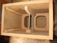
The third generation brace seems to be the way to go.") With sore knuckles after lots of tapping I now have only a faint hint of the 200 Hz resonance, and a much duller resonance on tapping.
With sore knuckles after lots of tapping I now have only a faint hint of the 200 Hz resonance, and a much duller resonance on tapping. 
Pictures tell the story much better, so here we go. The photos are taken looking down from the base of the speaker, with the bottom access panel removed. You can see the shelf brace that sits just below the driver (driver not installed yet). In the photo you can see the first generation brace towards the bottom of the photo, which is just a 150mm length of 25mm MDF on its side with a couple of holes in it. Its really just a support for the all-thread. This didn't make much difference to the resonance of the side wall. The second generation brace is at the other end of the all thread, near the top of the photo. It is designed to actually stiffen the wall, rather than just be a support for the all-thread. It worked quite a lot better.
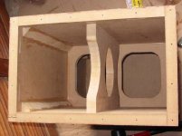
The second photo (next thread) shows the 3rd generation, which is a solid piece of 25mm MDF that spans the two walls, and this worked very well, as detailed above.
So the conclusion is that just having a post-type brace that connects two walls doesn't seem to do much for reducing wall resonances. Best to have something that stiffens the wall.
Thanks for your comments Omnifex. It is probably too late now, but what is a t-brace?
Mick
The third generation brace seems to be the way to go.
With sore knuckles after lots of tapping I now have only a faint hint of the 200 Hz resonance, and a much duller resonance on tapping. Pictures tell the story much better, so here we go. The photos are taken looking down from the base of the speaker, with the bottom access panel removed. You can see the shelf brace that sits just below the driver (driver not installed yet). In the photo you can see the first generation brace towards the bottom of the photo, which is just a 150mm length of 25mm MDF on its side with a couple of holes in it. Its really just a support for the all-thread. This didn't make much difference to the resonance of the side wall. The second generation brace is at the other end of the all thread, near the top of the photo. It is designed to actually stiffen the wall, rather than just be a support for the all-thread. It worked quite a lot better.
The second photo (next thread) shows the 3rd generation, which is a solid piece of 25mm MDF that spans the two walls, and this worked very well, as detailed above.
So the conclusion is that just having a post-type brace that connects two walls doesn't seem to do much for reducing wall resonances. Best to have something that stiffens the wall.
Thanks for your comments Omnifex. It is probably too late now, but what is a t-brace?
Mick
Attachments
Here's a t brace.......
Although they made a frame around the "t", you can
achieve the same results just adding the "t" to the
walls of the enclousure.
Due to so many different styles called Cross Bracing, I call
it a "t" brace.
For the record, this particular style, is the true meaning
of Cross Bracing.
You use 2 by 2's (Or in my case 2 by 4's, or 4 by 4's)
in the center of the box.
The good thing about this, is it takes less internal volume,
than tons of bracing in the box. Wrap some Fiberglass
around it, and, its good as gone, as far as the speakers
concern.
An externally hosted image should be here but it was not working when we last tested it.
Although they made a frame around the "t", you can
achieve the same results just adding the "t" to the
walls of the enclousure.
Due to so many different styles called Cross Bracing, I call
it a "t" brace.
For the record, this particular style, is the true meaning
of Cross Bracing.
You use 2 by 2's (Or in my case 2 by 4's, or 4 by 4's)
in the center of the box.
The good thing about this, is it takes less internal volume,
than tons of bracing in the box. Wrap some Fiberglass
around it, and, its good as gone, as far as the speakers
concern.
If you brace between two opposite walls, the stiffening effect might be much better, than a simple knocking test make you believe.
Remember that you excite both walls in the same direction (i.e. both from left to right or vice versa) with your mechanical "pulse". Simply because the panels are mechanically COUPLED by the brace! Though the whole thing is stiffer than one wall only.
Your driver however excites both panels inward or outward at the same time and therefore the brace works much better for this excitation mode than it does for your knocking test !
Regards
Charles
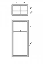
if you want to get tricky, you could try something like the following, where all the unbraced panel spans have different dimensions. this allows for multiple resonant frequencies in the cabinet walls, so the excitement response is spread out instead of focused at one frequency.
/andrew
/andrew
Attachments
I HATE TO SPOIL ANYBODIES FUN AND GAMES, BUT WHERE DO YOU GET THE 200HZ FROM?, ALSO AT RISK OF INJURING YOUR DIGITS EVEN MORE DID YOU HOLD YOUR EAR AGAINST THE ENCLOSURE WALL WHILE JOYFULLY RAPPING IT MAY I SUGGEST YOU TRY THIS AND SEE IF IT IS STILL AT THE FREQUENCY YOU DETERMINED INITIALLY I VENTURE TO SAY THE RINGING IN YOUR EARS WILL BE MUCH HIGHER AND FULL OF HARMONICS THAT YOU SHOULD TRY TO SUPPRESS ALA BBC METHOD AS THESE RINGING TONES WHEN EXITED BY THE WOOFERS WILL BE MUCH MORE AUDIBLE THAN FROM YOUR POOR FINGERS ALONE HAVE FUN WITHOUT PREJUDICE, BEST REGARDS, TJB
MAY I SUGGEST YOU TRY THIS AND SEE IF IT IS STILL AT THE FREQUENCY YOU DETERMINED INITIALLY I VENTURE TO SAY THE RINGING IN YOUR EARS WILL BE MUCH HIGHER AND FULL OF HARMONICS THAT YOU SHOULD TRY TO SUPPRESS ALA BBC METHOD AS THESE RINGING TONES WHEN EXITED BY THE WOOFERS WILL BE MUCH MORE AUDIBLE THAN FROM YOUR POOR FINGERS ALONE HAVE FUN WITHOUT PREJUDICE, BEST REGARDS, TJBphase_accurate said:Remember that you excite both walls in the same direction (i.e. both from left to right or vice versa) with your mechanical "pulse".
Phase accurate - you are quite right, and this is something that I had thought of. Unfortunately until I get the drivers mounted and can run some tests I can't really verify effectiveness of the simple brace between the walls.
QWAD!! - until I got to the third version of the brace it was quite easy to hear the frequency of the resonance after tapping. Its not a pure sine tone, but pure enough to hear that it was a G an octave below A 440Hz, which would be approximately 200 Hz. Once the bracing became more effective it became harder to hear the frequency, as it became a higher frequency sounding rap.
Once I have the drivers mounted I will be able to confirm this better by running some sine tones through them and listening with a stethescope for vibration in each panel. I'll give you an update then. As I've said before, all I'm aiming to do is to push resonant frequencies up past 400 Hz or so which is well past the 200 Hz XO frequency.
Faust - I have seen suggestions of not having the brace in the centre of the panel so that the excitation frequencies of each divided section are different, and I tried this. However it seemed that having it in the middle worked best in terms of giving the dullest thud. Unfortunately the 3rd generation brace is not glued in yet, so the tests may not be truely representative.
Mick
- Status
- This old topic is closed. If you want to reopen this topic, contact a moderator using the "Report Post" button.
- Home
- Loudspeakers
- Multi-Way
- Cross brace not working