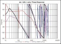
Attached please see my latest phase response chart.....I have no idea how to interpret it and very little knowledge about phase response and how it effects sound........Will some of you please help me interpret this chart and answer a few questions for me?.....What does this chart represent?.....How does this relate to how the speakers actually sound?.........What in crossover design effects phase response?.......What are the chart characteristics of a good phase response? ....What am I looking for to achieve a good phase response?.....And any other information you can give me that will help me in understanding phase response..........Thank You for any help I can get......Omni
Attachments
What does this chart represent?
If you put a sine wave into a speaker you get one out of the same frequency but amplitude scaled and phase shifted. A frequency response plot shows, as a function of frequency, what the amplitude scaling is, in dB. A phase plot shows, as a function of frequency, what the phase shift is. Thus, if a plot says 120 degrees at 1 kHz, when you put a 1 kHz tone into the system, the output is a 1 kHz tone shifted 120 degrees.
How does this relate to how the speakers actually sound?
If you're talking about the phase of a given completed system, then my answer is that it doesn't matter much. It is possible to screw up phase in such a way that it will be audible, but for anything reasonable you might do, the phase response of the end system isn't much of a concern.
When I say that, I mean that phase isn't inherently a concern. Phase is a very important thing to keep track of when you are designing and tuning a system! If you have two sources that are playing at the same frequency (drivers at crosspoint), then the phase response of each of them tells you how they will sum. For example, if they are shifted by 180 degrees and of the same amplitude, they will cancel each other.
What in crossover design effects phase response?
In the system, the drivers have phase shift, the electronics have phase shift, and there is phase shift from the propagation time. In the passive components and the speaker, the phase shift is essentially from elements (springs, masses, inductors, capacitors, acoustic masses, acoustic springs) storing energy and then releasing it later.
What are the chart characteristics of a good phase response?
For the most part, it isn't as simple as good and bad. It's more about being able to optimize given a situation. For example, in a crossover you most likely want the phase responses of the two sections in the crossover region to be the same so they sum perfectly.
What am I looking for to achieve a good phase response?
Again, the curve isn't inherently worth much (as opposed to say, a FR graph), but it tells you what the system is doing. That allows you to manipulate other things to optmize things that do matter inherently.
Hi
An acoustic phase measurement shows when in phase the pressure is produced relative to the driving signal. It is the systems magnitude and phase, which govern the systems response to any signal for example its impulse response.
Your phase plot seems to show the acoustic phase plus the phase shift caused by time delay. To see actual acoustic phase, one must remove all Time delay related phase rotation. In other words, a loudspeakers acoustic phase response is not affected by distance to microphone other than all frequencies being delayed equally.
Thus, when you remove the phase shift related to time, one has acoustic phase.
Also then the distance to the ear has no effect on the speakers ability to preserve the input waveshape again because all frequencies are delayed equally.
Waveshape is preserved if the phase is near zero or –180 from an inverting system,in normal multiway speakers the phase shift prevents the speaker from preserving waveshape. Acoustic phase can be thought of as a frequency dependent change in time, a difference between when one frequency is produced and another.
Simple but sort of and described first by Richard Heyser, but many popular measurement systems have a plot for phase but it is not an actual measurement of acoustic phase.
That can be tested if you have a DSP speaker controller; the controller is set up with a high pass and low pass filter slopes plus a time delay to act like the mic to speaker distance. Then the controller is wired in as a perfect speaker in a noise free environment.
If the indicated phase is the same / similar to the actual phase from the filter set, then it measures phase.
Here are some posts with some graphs that talk about this.
http://srforums.prosoundweb.com/index.php/mv/msg/22292/0/40/16795/
If your measurement system has some kind of time setting, try looking slightly earlier in time than your current reference.
Hope that helps,
Tom Danley
Thank you both for the replies as I will probably have to study them further to digest your insights.........Can you provide any interpretations of those particular graphs that I posted?.......I have studied various aspects of crossover design and am now in the process of tweaking my current crossover via listening and the use of Jeff Bagbys' passive crossover designer.......My Frequency Response charts seem to pretty much reflect what I am hearing during listening tests, but I guess I was sort of wondering whether I am missing something or need to be concerned with the Phase charts as I change component values during my tweaking process...........Respectfully.......Omni
For you, all I'd worry about is getting the phase of tweeter and woofer at the crossover point to be the same or at least very close.
Basically just get the phases for each driver to 'cross' each other at or very near the crossover point. Phase of the individual drivers isn't what you're concerned about. It's the phases relative to each other that you're concerned with.
How the frequency response of each driver will combine to create the total frequency response of your speaker depends on phases of the drivers relative to each other. Like Rybaudio said, if they're 180 degrees out of phase (basically going the opposite direction) then any sound at that frequency will cancel.
To remove the time of flight phase shift you need to perform a hilbert transform on the frequency response data. This will get you the minimum phase of the driver which you can use in crossover optimization. You can use the FRD spreadsheet from the FRC to do that.
Once you put the driver in a crossover, its minimum phase shifts again. To get the phases of each driver to line up at the crossover point, you need to tweak the values of the components in the crossover. You can also use asymmetrical crossover slopes or change the frequency of the crossover to try and get the phases to line up better at the crossover point.
QUOTE]Originally posted by omni
Attached please see my latest phase response chart.....I have no idea how to interpret it and very little knowledge about phase response and how it effects sound........Will some of you please help me interpret this chart and answer a few questions for me?.....What does this chart represent?
[/QUOTE]
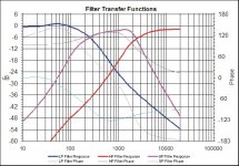
It is hard to say, is this the acoustic response of the woofer and XO? The plot says LP HP and BP but I don't see the frequency response for the tother two drivers. Your second graph is clearly the XO transfer functions and their phase response. This doesn't matter at all for what you are asking. All the matters is the frequency response of the driver and XO together, the acoustic response.
As other have said phase impacts how the drivers sum together. For drivers to integrate properly in the XO region their acoustic frequency and phase response (driver + XO) has to match the target response frequency response and phase for the drivers to sum properly.
The target spl and phase response are the acoustic XO slopes you are shooting for in your design. For example, a 2500 Hz 4th order Linkwitz Riley XO as your target implies that both your drivers will be in phase at the design point. So if the measured phase of your woofer and XO should be the same as that of the tweeter. In fact for best summation, they should be in phase well on either side of the XO point as well. Just to be clear though, the target phase difference between the drivers, either 0, 90, or 180 degrees is determined by the target slopes. So in phase is only correct for those XOs that sum properly when they drivers are in phase. Others such as the 1st order Butterworth require that the drivers be 90 degrees apart at the XO point and so on.
A XO and driver combination is, in most cases minimum phase which means that there is a direct relationship between the frequency response and phase. If you XO changes the frequency response in any way other than just changing the overall level (turning the volume down), the phase will also change to match.
Good phase response means that your acoustic freq and phase for each driver/XO matches the target response over a wide range. It also means that for the drivers to sum properly they must also have the proper relative phase offset as the target.
Here is a great paper on phase response and it's effects by John Kreskovsky
http://www.geocities.com/kreskovs/Phase-B.html
Regards,
Dennis
Attached please see my latest phase response chart.....I have no idea how to interpret it and very little knowledge about phase response and how it effects sound........Will some of you please help me interpret this chart and answer a few questions for me?.....What does this chart represent?
[/QUOTE]
It is hard to say, is this the acoustic response of the woofer and XO? The plot says LP HP and BP but I don't see the frequency response for the tother two drivers. Your second graph is clearly the XO transfer functions and their phase response. This doesn't matter at all for what you are asking. All the matters is the frequency response of the driver and XO together, the acoustic response.
omni said:.....How does this relate to how the speakers actually sound?
[/B]
As other have said phase impacts how the drivers sum together. For drivers to integrate properly in the XO region their acoustic frequency and phase response (driver + XO) has to match the target response frequency response and phase for the drivers to sum properly.
The target spl and phase response are the acoustic XO slopes you are shooting for in your design. For example, a 2500 Hz 4th order Linkwitz Riley XO as your target implies that both your drivers will be in phase at the design point. So if the measured phase of your woofer and XO should be the same as that of the tweeter. In fact for best summation, they should be in phase well on either side of the XO point as well. Just to be clear though, the target phase difference between the drivers, either 0, 90, or 180 degrees is determined by the target slopes. So in phase is only correct for those XOs that sum properly when they drivers are in phase. Others such as the 1st order Butterworth require that the drivers be 90 degrees apart at the XO point and so on.
omni said:.........What in crossover design effects phase response?
[/B]
A XO and driver combination is, in most cases minimum phase which means that there is a direct relationship between the frequency response and phase. If you XO changes the frequency response in any way other than just changing the overall level (turning the volume down), the phase will also change to match.
omni said:.......What are the chart characteristics of a good phase response? ....What am I looking for to achieve a good phase response?
[/B]
Good phase response means that your acoustic freq and phase for each driver/XO matches the target response over a wide range. It also means that for the drivers to sum properly they must also have the proper relative phase offset as the target.
omni said:.....And any other information you can give me that will help me in understanding phase response..........Thank You for any help I can get......Omni [/B]
Here is a great paper on phase response and it's effects by John Kreskovsky
http://www.geocities.com/kreskovs/Phase-B.html
Regards,
Dennis
I don't fully agree with everything that has been said here. First, there are things that can make a phase response bad, in that, strong phase shifts coupled with a difficult load impedance (4 ohms) can make a speaker difficult to drive. Additionally, these strong shifts when coupled with certain amplifiers, such as tube amplifiers, can actually cause the amplifier to interact with the speaker in such a way as to change its response. This is why you commonly see speaker designers refer to a speaker as being a good or bad match with tube amplifiers, or a difficult load.
The second issue I take with what is said is that it doesn't address a theoretical ideal important in crossover design. In a perfect way, you would have a speaker which has all the drivers hand off to the next driver with no impact on amplitude and NO CHANGE IN PHASE. However, that isn't possible, but, you can come close. So while for the average designer only interested in a flat amplitude response you can ignore phase, it is important if you are also trying to build a speaker which can cleanly pass the input signal unchanged. Again, this is theoretical as it isn't possible in the real world, but again, you can come close. The name for such crossover topologies are transient perfect, quasi-transient perfect, minimum phase, or I have even heard phase delayed. These all use methods to minimize or eliminate the phase shifts which cause the incoming signal to also be shifted. One commonly referred test for this is a speakers ability to cleanly pass a square wave. Elsinore project The Elsinore project is a good place to read a bit on an attempt to have minimum phase shifts in the crossover as to pass transient signals perfectly.
Now, having said all that, most speaker designers do ignore the phase response and do not attempt transient perfect crossover topologies because doing so often must be at the expense of the amplitude response. It's also a theoretical ideal that can not be achieved, merely approximated, and I think most designers think the average consumer will find a smooth amplitude response more important. I think that a good speaker designer takes into account all aspects of a speakers design, including its transient response (i.e. step response) which exists in the time domain, as well as its amplitude response. It's also very important to look at the phase response in relation to the impedance plot, as again, if you have a strong negative phase angle (say -120 degrees) coupled to an impedance of 3 or 4 ohms, many amplifiers will have trouble with that. Such a design would more than likely cause the average consumer receiver to shut down, and probably give a good many separate amplifiers a bit of trouble too.
Oh I realized that I was talking about both acoustic and electric phase almost interchangeably, and that might be confusing. Acoustic phase is what really impacts the transient performance, and can be affected with delay (be it physical or electrical), where as electrical phase is what causes the load problems for amplifiers, and can not be physically changed, only electrically. Moving a driver in or out in relation to the tweeter, or changing its angle will not have any impact on its electrical phase, but will have an impact on its acoustical phase. Acoustical phase is what is important for a good pass band and good driver integration, electrical phase is what is important for a speakers drivability. But...to make things a little more confusing, they are directly related to each other.
pjpoes said:I don't fully agree with everything that has been said here. First, there are things that can make a phase response bad, in that, strong phase shifts coupled with a difficult load impedance (4 ohms) can make a speaker difficult to drive. Additionally, these strong shifts when coupled with certain amplifiers, such as tube amplifiers, can actually cause the amplifier to interact with the speaker in such a way as to change its response. This is why you commonly see speaker designers refer to a speaker as being a good or bad match with tube amplifiers, or a difficult load.
I understand what you are saying, but for Omni and others, the phase you are talking about is the impdeance phase derived from the impedance of the drivers and XO. The further the system impdance deviates from a resistive load (and a 0 degree impedance phase angle) toward an inductive or capacative load, especially into a low impedance, the more difficult the load is for an amplifier to drive.
pjpoes said:The second issue I take with what is said is that it doesn't address a theoretical ideal important in crossover design. In a perfect way, you would have a speaker which has all the drivers hand off to the next driver with no impact on amplitude and NO CHANGE IN PHASE. However, that isn't possible, but, you can come close. So while for the average designer only interested in a flat amplitude response you can ignore phase, it is important if you are also trying to build a speaker which can cleanly pass the input signal unchanged. Again, this is theoretical as it isn't possible in the real world, but again, you can come close. The name for such crossover topologies are transient perfect, quasi-transient perfect, minimum phase, or I have even heard phase delayed. These all use methods to minimize or eliminate the phase shifts which cause the incoming signal to also be shifted. One commonly referred test for this is a speakers ability to cleanly pass a square wave. Elsinore project The Elsinore project is a good place to read a bit on an attempt to have minimum phase shifts in the crossover as to pass transient signals perfectly.
[/B]
Well for Omni who is just trying to understand how acoustic phase affects his system, transient perfect speaker design is probably a bit more than he needs right now. In fact John's paper I linked to does touch on how the phase response impacts the transient response. This is in fact more than he needs right now but the paper does a good job of explaining how the acoustic phase impacts the driver summation which is why I linked to it.
Also to clarify your point your point that a person not interested in transient perfect and wants flat frequency response can ignore phase, this is generally true if you are talking about deviation from zero phase shift in the system acoustic phase. The designer however must be very aware of the phase response of each single driver and it's XO in relation to the target phase and the phase of the other driver. If you don't, you may end up with a flat response (on axis) but the sound will not be that great especially off axis.
Again, not disagreeing with what you have said, just trying to clarify a few things for others.
Regards,
Dennis
Thanks Dennis, that is well said. I agree that it appears to be outside what omni said he was looking for, but sometimes it can be posts like these that become misconstrued later on. Someone will say what you have said, someone else will quote it or search it, and suddenly those of us who know better are being told that phase is unimportant, and suddenly this whole area of crossover science is being neglected all from a misunderstanding.
On a tangent here, I'm not sure where it came from, but you here that transient perfect crossovers are easily achieved through simple 1st order crossovers. Having tried that as part of a series of experiments I was doing, I can say without a doubt that they are quasi, not true. At first I thought it must have been my test rig, but I sent my results to some well known designers, and they told me these were in fact consistent with their own experimental results, as well as those of most of the work in this area. I'm starting to think that the only way to get a true transient perfect crossover is going to be with the use of subtractive delay. Even then, I bet it will only be transient perfect at the crossover itself. Then you have the drivers which can be ever so slightly off in placement, problems or inconsistencies with the drivers, etc. which all could cause the system not to pass transients perfectly.
On a tangent here, I'm not sure where it came from, but you here that transient perfect crossovers are easily achieved through simple 1st order crossovers. Having tried that as part of a series of experiments I was doing, I can say without a doubt that they are quasi, not true. At first I thought it must have been my test rig, but I sent my results to some well known designers, and they told me these were in fact consistent with their own experimental results, as well as those of most of the work in this area. I'm starting to think that the only way to get a true transient perfect crossover is going to be with the use of subtractive delay. Even then, I bet it will only be transient perfect at the crossover itself. Then you have the drivers which can be ever so slightly off in placement, problems or inconsistencies with the drivers, etc. which all could cause the system not to pass transients perfectly.
Thank you so much for your replies, and as I study them to learn about this aspect I am still a bit confused about how to actually read the charts I posted.......Can you teach me how to read these charts so that I can gain more of an understanding of what you guys have posted so far?..............Can anyone describe what they see on these particular charts and provide a vivid description of whats actually happening here?.........Omni
True 1st order acoustic slopes, especially those that match the target response far out into the stop band are very difficult to achieve, but not impossible. See the measurements of the Dunlavy SC-VI for a prime example.
http://stereophile.com/floorloudspeakers/162/index9.html
But I have seen the XO for this speaker and it is very complex, having some 30+ components.
I have found that for a passive approach, the B&O filler driver approach works well as you only need to attain 1st order slopes on the filler driver while the woofer and tweeter get 2nd order slopes. Hence your XO is simpler, the selection of suitable drivers is greater and the demands placed on the drivers are less. My own unpublished TP 3 way used the Scan Speak Revelator woofers, a vifa full range driver and the Seas Millenium tweeter. But because of the MFTFM layout ended up being a very large speaker and just too big for the HT.
The subtractive delay approach is a good option if you are going active but is not doable with passive components. The subtractive delay approach by allowing much steeper slopes eliminates a number of the problems inherent in lower order design methods.
Any TP approach is going to be compromised by the inherent bandpass nature of all real drivers. For the system to truly be transient perfect the system response would have to extend from DC to infinity. Of course this isn't possible but designs such as the Dunlavy above, John K's, and others can get fairly close. There is also an article in the recent Audio-Xpress magazine about this very subject.
Regards,
Dennis
Hi Omni
I can’t do much so far as interpretation as my eyes are used to seeing acoustic phase with the time delay removed.
If you are able to sample at slightly earlier time, your phase response will have less wrapping.
Can you save the summed mag and phase as a 3 row text file?
From that point, what is undesirable are changes in phase as this represents a change in time going from one frequency to another.
In a normal crossover, the acoustic phase changes with a rate of 90 degrees per crossover order plus the drivers phase shifts.
The summation if perfect is an all pass response, phase changes while amplitude does not.
All crossover filters are time delays, the high pass signal emerges first with the lf one emerging later. A normal 4th order filter summation will show 360 degrees of phase rotation going from well above to well below crossover.
If one put an “impulse” signal in to the speaker, a signal that has all frequencies of interest in one short spike, sound will emerge for the speaker not as one impulse but separated in time according to frequency via its acoustic phase response.
There is no real agreement on how important time coherence is and unfortunately it has become a highly over used and close to meaningless marketing word.
A speaker that is or is close enough to having one radiation time over a broad band can reproduce the signal it is fed, for example a square wave is easy to see and is broad band.
Pipoes said “In a perfect way, you would have a speaker which has all the drivers hand off to the next driver with no impact on amplitude and NO CHANGE IN PHASE. However, that isn't possible, but, you can come close. So while for the average designer only interested in a flat amplitude response you can ignore phase, it is important if you are also trying to build a speaker which can cleanly pass the input signal unchanged. Again, this is theoretical as it isn't possible in the real world, but again, you can come close. The name for such crossover topologies are transient perfect, quasi-transient perfect, minimum phase, or I have even heard phase delayed. These all use methods to minimize or eliminate the phase shifts which cause the incoming signal to also be shifted. One commonly referred test for this is a speakers ability to cleanly pass a square wave. Elsinore project The Elsinore project is a good place to read a bit on an attempt to have minimum phase shifts in the crossover as to pass transient signals perfectly.
I would disagree some, it is possible to get pretty close and not just as a computer model.
Also, as mentioned in the reality test, many measurement systems can’t actually measure acoustic phase, it is not surprising that there are many more pretty computer predictions than measured results.
I say that, as this acoustic phase stuff has been a keen interest of mine for quite some time.
I know this solution is not for home use, they are too big and ugly, have too much headroom / driver costs, but some years ago I found a way to combine the outputs of multiple drivers with a passive crossover, such that the system radiates as if it were one source, no lobes or nulls and constant directivity.
If interested, there is a CLF (common Loudspeaker Format) file and viewer that allows one to see the measured broadband spherical radiation pattern in 3D, over the whole range from any angle.
The viewer and SH-50 data files can be downloaded at;
http://www.danleysoundlabs.com/technical downloads.html
In that development process, it also involved trying to make all the drivers combine, to act as one source in time as well and actually all the requirements are tied together.
My goal was to make something that measured as well as or close to a Manger in time (The best speaker in time I had ever measured), but could be used 40dB or 50 dB louder and have constant directivity which is critical as the room size goes up (and still important in the living room), they are not your normal PA speaker.
Here is a post that has square waves (over a reasonably broad band) from an actual speaker, not in an anechoic chamber.
http://www.diyaudio.com/forums/showthread.php?threadid=71824&highlight=
While that box is a 3-way system and has 2X12 inch woofers, 4X5inch mids and a compression driver, it does produce a nice measured wide band impulse response.
On page 5 here is the measured impulse, GD etc responses (@24KHz bandwidth).
http://www.danleysoundlabs.com/pdf/danley_tapped.pdf
I was curious what hifi Horn types would think so for fun the company (who is not very familiar with or interested in the hifi market ) sent a pair to Oswald’s Mill this year.
Oswald’s mill is a high efficiency speaker and Tube related get together and the fellow who runs it was curious about the speakers.
I am trying to get the others at the company more interested to be honest as I think there are possibilities for the home, some people still have large speakers..
Anyway I couldn’t go, no one from the company went but we did get some casual feedback on a forum from a hifi perspective about what this “Pro-sound” horn system sounds like to him and some other guy who’s boss lent him several other of our speakers.
http://www.audioasylum.com/forums/hug/messages/13/134188.html
Here’s the thing, if your trying to resolve the phase and your modeling it in a computer, somewhere along the line you need to find out if your phase measurements are right.
A real issue is that many systems do not actually measure acoustic phase, they have a nice plot, maybe a minimum phase derivation but that isn’t the same as a measurement.
A speaker, particularly when it is beginning to have directivity or facing a changing radiation resistance, may show an amplitude change that doesn’t have the normal amount (less or more) than the minimum phase assumption.
If you guys are seriously pursuing the “time grail”, do the reality test I linked to and confirm you can measure actual acoustic phase in the first place and that you’re not just dealing with a nice trace.
Electrically a driver appears to be a collection of series and parallel R’s, L’s and C’s, it produces an impedance and phase angle one expects for that collection and connection of bits.
There is no time delay here, one directly reads the mag and phase AND this is exactly the condition one needs to achieve to read a drivers acoustic phase as well.
All of the fixed time delay has to be removed, that leaves the acoustic phase (assuming it measures actual acoustic phase in the first place)..
As a load, the greater the phase angle the more heating the output stage shows, a 90 degree load angle requires the output stage to deliver the maximum current while the output Voltage is zero instead of maximum (minimum Voltage across the device, heating is V*I) for a resistive load. Most amplifiers won’t allow operation into that much reactance, current or V* I limiting engages.
Typically you don’t see even a big heavy woofer that comes close to 90 degrees load angle though .
The load angle changes a great deal over frequency and falls to a resistive value at Rmin in the midband..
Keep in mind a woofer is an R/C low pass filter, you are using it on is “falling off” slope and that is to compensate for the improving radiation resistance as the frequency climbs, the two cancel viola, “Flat response”.
So, as one increases the frequency from Fb, one finds the load is increasing dominated by the series R and not the C (mass transformed into load).
As the “output” from the driver is across the C, the acoustic phase of a woofer where its most reactive, also lags approaching –90 degrees.
A “time grail” issue for a direct radiator woofer ( a radiator that is acoustically small) is that all by itself, it has frequency dependent phase shift (or a spreading of an impulse in time).
From one woofer alone, the high frequencies come out first and the bottom, last.
Add a vent or higher order box and one finds the time is more jumbled up and extended, for example at the low cutoff of a vented box, the LF end is delayed a time approximately equal to 1 / 2 wavelength at that Vent frequency.
Anyway, hope that helps, try the phase measurement reality test if you can.
Best,
Tom Danley
I don't think that the original poster wanted to know everything about transient perfect. Just what those zig zags represent and what to watch about them. It developed to a nice discussion though.
Anyway if someone wants some square waves in his living room, the simplest way is to use a Jordan in a closed or TL box IMO.
Anyway if someone wants some square waves in his living room, the simplest way is to use a Jordan in a closed or TL box IMO.
pjpoes said:The second issue I take with what is said is that it doesn't address a theoretical ideal important in crossover design. In a perfect way, you would have a speaker which has all the drivers hand off to the next driver with no impact on amplitude and NO CHANGE IN PHASE. However, that isn't possible, but, you can come close. So while for the average designer only interested in a flat amplitude response you can ignore phase, it is important if you are also trying to build a speaker which can cleanly pass the input signal unchanged.
The goal of a speaker is to reproduce something that we listen to. Given that, I say that phase distortion is only worth considering if it is audible on most program material, and if so, its design importance is proportional to its offensiveness. If one takes that position, phase distortion in almost anything a DIYer is going to do doesn't matter. Here's how I came to this position and how I reccomend anyone go about it:
1) Read the available research on the matter. There have been a few studies that put thresholds on group delay audibility at different frequencies. Compare those with the group delay of, say, an LR4 or LR8 crossover. Also, keep in mind that these are minimum thresholds that it takes training and specialized program material to detect.
2) Isolate the effect in the ideal case: use a computer program to process music and then A/B the processed/unprocessed over a good set of headphones. This way nothing except the phase response changes. Matlab has several useful functions built in that allow you to do this. There is even a function, iirgrpdelay, that will create a filter with an arbitrary specified group delay. What I found was that this type of distortion is inaudible with anything I'd ever want to do and when it does become audible, it's not offensive unless you very carefully select program material or you do something really stupid.
Thus my position is that one should simply not worry about the phase of the system as an end itself, unless you're doing something well out of the ordinary (e.g. very high order filters).
Hi Salas
“I don't think that the original poster wanted to know everything about transient perfect. Just what those zig zags represent and what to watch about them.”
If he can save the summed mag and phase as a 3 row text file, I can unwrap it and take a guess.
Rybaudio, I would point out that you get the result you test for, under those conditions.
For example, if you take your speakers magnitude and phase and convolve a musical test signal you are “hearing” the speaker through your headphones.
In a sense you are but regardless of how good your headphones are, playing that same material through the speakers produces an obviously different result.
It is the same for phase tests, these simulations fail to account for the fact that the drivers are in separate physical locations and this also causes nulls and lobes in directions the microphone isn’t, which you hear in your room.
Phase changes at crossover in a loudspeaker system are usually more than just an “on axis” curiosity, they strongly effect where the sound goes. If it was customary to measure hifi speakers in all directions, “spherically”, one would see “where the sound goes” has a great deal to do with the driver spacing and crossover details.
In this case, how far the speakers direct field extends is also related to where the sound goes.
The phase issues at the source can give your ears aural clues as to where the speaker is in depth too. In a mono setup, I have found that all things being equal, the more coherent the source is in time, the harder it is to “hear” how far away the speaker is (separate from the recording), if that makes sense.
Speakers give out clues as to their location; while playing, you can usually easily hear how far away they are with your eyes closed, some have very strong clues and some of these clues are related to these phase / time issues. Reducing the clues makes for a stronger stereo image if it is present in the recording.
If you ever have a chance to listen to a Manger, stand a few feet away and listen, you will have a very hard time locating how far away it is with your ears.
The Manger, while crippled in the loudness department, is the best speaker “in time” I have ever measured.
Best,
Tom Danley
Hi Tom
I believe that a nicely behaving in time domain speaker, has some desirable side benefits to boast on top of the audibility controversial arbitrary axis perfect impulse.
I agree with the localization findings of yours, I also feel a sense of better intelligibility in time coherent designs.
I believe that a nicely behaving in time domain speaker, has some desirable side benefits to boast on top of the audibility controversial arbitrary axis perfect impulse.
I agree with the localization findings of yours, I also feel a sense of better intelligibility in time coherent designs.
salas said:Hi Tom
I believe that a nicely behaving in time domain speaker, has some desirable side benefits to boast on top of the audibility controversial arbitrary axis perfect impulse.
I agree with the localization findings of yours, I also feel a sense of better intelligibility in time coherent designs.
Speculation alert: most tests for phase sensitivity are ambiguous because they focus on higher parts of the spectrum, around typical crossover frequencies such as 2 or 3 kHz. Typical audio has comparatively little energy in that range, so transient impact wouldn't be overly affected by non-minimum phase. What might be really important for palpability is phase coherence below 1 kHz, perhaps below 500 Hz, because
a) music has most of its energy around 200 Hz and
b) preserving phase below 500 Hz would maintain most of the wavefronts for instruments such as drums, which depend on transients for their effect.
This actually kind of hoses one of my current designs because I have a 4th order Linkwitz-Riley at 100 Hz, so that means I need to set up a FIR active crossover sooner rather than later. Oh well. Prototype early, prototype often.
Tom Danley said:If you are able to sample at slightly earlier time, your phase response will have less wrapping.
Can you save the summed mag and phase as a 3 row text file?
Tom - just to note. He's simulating x-overs using the FRD Passive Crossover spreadsheet. A handy-dandy bit of work, but I am not sure it will give you what you are looking for. It does allow for shifting each driver in the X-Y & Z axis - and also a simulated listening distance.
The default settings are for all drivers at the same point and a listening distance of 2 meters. Would it help you if the listening distance were other than 2 meters?
As for bringing things aout as a text file, it should be possible via the "Output to FRD file" button. That might be what you need.
Thanks to all for the great responses! Interesting reading.
Tom Danley said:Rybaudio, I would point out that you get the result you test for, under those conditions.
For example, if you take your speakers magnitude and phase and convolve a musical test signal you are “hearing” the speaker through your headphones. In a sense you are but regardless of how good your headphones are, playing that same material through the speakers produces an obviously different result.
It is the same for phase tests, these simulations fail to account for the fact that the drivers are in separate physical locations and this also causes nulls and lobes in directions the microphone isn’t, which you hear in your room.
Phase changes at crossover in a loudspeaker system are usually more than just an “on axis” curiosity, they strongly effect where the sound goes. If it was customary to measure hifi speakers in all directions, “spherically”, one would see “where the sound goes” has a great deal to do with the driver spacing and crossover details.
In this case, how far the speakers direct field extends is also related to where the sound goes.
The phase issues at the source can give your ears aural clues as to where the speaker is in depth too. In a mono setup, I have found that all things being equal, the more coherent the source is in time, the harder it is to “hear” how far away the speaker is (separate from the recording), if that makes sense.
Speakers give out clues as to their location; while playing, you can usually easily hear how far away they are with your eyes closed, some have very strong clues and some of these clues are related to these phase / time issues. Reducing the clues makes for a stronger stereo image if it is present in the recording.
If you ever have a chance to listen to a Manger, stand a few feet away and listen, you will have a very hard time locating how far away it is with your ears.
The Manger, while crippled in the loudness department, is the best speaker “in time” I have ever measured.
Best,
Tom Danley
Tom, I'm not sure that I understand what you're saying here. You have no disagreement from me that the position or far field anglular dependence of the speaker's transfer function (phase and magnitude) is important and that phase is important to keep track of when designing the speaker. What I aimed to isolate was the audibility of the phase response itself, and I believe the test did exactly that.
The accounts of the subjective impression of time-coherence is interesting, but I have to wonder if it really is a causal relationship or what you have observed is coincidence (no pun intended). The way to test that is to take a speaker that is time-coherent, say a Manger from your example, and place a switchable allpass filter upstream (or have a cd with processed/unprocessed tracks). That way, when you A/B the allpass on/off, the only thing that changes is the phase. If your hypothesis is correct, then it would be harder to hear how far away the speaker was without the allpass, for example.
Part of the reason I went with headphones was because a couple papers I was reading compared threshold detection levels for headphones and in-room and the consensus seemed to be that headphones have a lower detection threshold. If that is correct, then what I've found applies to the test I suggested in the previous paragraph and consequently to your claim.
- Status
- This old topic is closed. If you want to reopen this topic, contact a moderator using the "Report Post" button.
- Home
- Loudspeakers
- Multi-Way
- Phase response inquiry