I have to re-mount a JBL 2245H in an enclosure FAR too small for it and was thinking of using an aperiodically-vented approach. It's been so long since I have used this kind of loading that I forgot exactly how to tune the vent. It seems to me that I put a resistor (1 k ohm?) in series with the driver and measured the voltage drop across it as I changed the stuffing in the vent but I'm not certain of this. Any clues?
I'm not sure I will have a fully answer for you, but lets see if this helps. What you suggest would be no different than a method more measuring impedance, essentially. An aperiodic enclosure is essentially an under sized enclosure with an inappropriately tuned vent, thus it will have a pretty high resonant frequency. You then block the vent with a lossy material of sorts, which breathes, but poorly. This will progressively damp and lower the resonant frequency until you get to the desired level. This is measurable via the impedance, as the impedance will be very high at the zero motion point, or resonant tuning frequency. To tune this, you would simply find the resonant frequency, and keep adding until that frequency is lowered. However, I'm pretty sure it will both lower the resistance, at that resonant frequency, but also lower the Res. freq. and thus require that you readjust your test tone until you "refind" the res. freq. Thus a quicker method would simply be to use an impedance measurement device. A wallen jig or woofer tester would work if you have access to either.
The only test equipment I have is a frequency generator, oscilloscope and a digital multi-meter so that's what I'll be working with.
As I said, I've done this before with just a frequency generator and a voltmeter, but it was about thirty years ago and I've lost touch with the method I used.
This is a one-time procedure (I have only one JBL 2245H), so I'm not going to go out and get more test equipment.
As I said, I've done this before with just a frequency generator and a voltmeter, but it was about thirty years ago and I've lost touch with the method I used.
This is a one-time procedure (I have only one JBL 2245H), so I'm not going to go out and get more test equipment.
I would presume you were trying for the amount of stuffing that gives the flattest impedance without double humps. Double humps means it is acting like a vented box, and higher single peaks means it is acting like a sealed box.
Another way of testing is with a click box. Wire up a quiet-operating switch in series with a 1.5V battery wire this to the speaker terminals, click the switch on and off and you are looking for the click when it turns off to be similar to the click when it turns on. Leave the vent open and then seal it with something airtight to hear the two extremes. Experiment from there.
Another way of testing is with a click box. Wire up a quiet-operating switch in series with a 1.5V battery wire this to the speaker terminals, click the switch on and off and you are looking for the click when it turns off to be similar to the click when it turns on. Leave the vent open and then seal it with something airtight to hear the two extremes. Experiment from there.
These curves describe what happens when damping in a bass-reflex port increases. I suppose that is what RonE meant?
An externally hosted image should be here but it was not working when we last tested it.
this is a suggested method from a guru...
(not me,") ),
),
without speaker measurement software, it may be a little tedious, but worth the effort. For what it's worth, me and my audio partnerr are doing just this. But we didn't shrink the box and add aperiodic vents, we've left the closed box size alone and am using the aperiodic vents simply to reduce the impedance amplitude (and increase the output) at or near Fs
(not me,
),- start with 1/2 the cone area, and 1" thick uncompressed fibreglass or long hair wool (or Dacron)
- play test tones to discover or get to the Fs of the driver in enclosure
- use a DMM, set to AC Volts
- put a 10k, 10W resistor between amp+ and speaker+, play test tones
- add or subtract "stuffing" (flow resistance) until the flattest set of values occurs. These lowest set of values should be approximately 50% in amplitude compare to ported or sealed box
without speaker measurement software, it may be a little tedious, but worth the effort. For what it's worth, me and my audio partnerr are doing just this. But we didn't shrink the box and add aperiodic vents, we've left the closed box size alone and am using the aperiodic vents simply to reduce the impedance amplitude (and increase the output) at or near Fs
this is a suggested method from a guru...
(not me, ),
without a speaker software setup, it may be a little tedious, but worth the effort. For what it's worth, I am doing just this. But I didn't shrink the box and add aperiodic vents, we've left the closed box size alone and am using the aperiodic vents simply to reduce the impedance amplitude (and increase the output) at or near Fs
(not me,
),- start w/ 1/2 the cone area, and 1" uncompressed fibreglass or long hair wool (or Dacron)
- play test tones to discover or get to the Fs of the driver in enclosure
- use a DMM, set to AC Volts
- put a 10k, 10W resistor between amp+ and speaker+, play test tones
- add or subtract "stuffing" (flow resistance) until the flattest set of values occurs. These lowest set of values should be approximately 50% in amplitude compare to ported or sealed box
without a speaker software setup, it may be a little tedious, but worth the effort. For what it's worth, I am doing just this. But I didn't shrink the box and add aperiodic vents, we've left the closed box size alone and am using the aperiodic vents simply to reduce the impedance amplitude (and increase the output) at or near Fs
Fiberglass..
How many times I read that fiberglass is toxic and dangeros for lungs... for me, positioning a such material in a breathing vent is a stupid thing. In a couple days your room will be impregnated with microscopical glassy parts. And you and your family will breathe them.
Wool or sintetic stuff would be better.
Only my two cents.
I am currently building a pair of speakers with aperiodic vents and I have read suggestions of 'tuning' them via impedance curve measurements (which I shall do) and adjusting for the flattest result, but wouldn't the flattest impedance curve from a given drive unit and cabinet be with the vent completely open without damping material of any kind...or am I missing something?
Have you checked out the link below and the additional links it gives at the bottom of the page?
Aperiodic Loudspeaker Enclosure Design
A so called 'aperiodic' enclosure has more in common with a sealed enclosure than a bass reflex enclosure.
The idea of including a resistive vent is to reduce the amplitude of the single impedance peak which is characteristic of a closed box. This results in better amplifier matchng and control at low frequencies.
Thanks for the reply. Yes, I've seen those web pages and I'm aware of the improved transient response and flattened impedance peak at resonance, but my query is regarding finding the optimum membrane density via impedance measurements.
As an example let's assume a starting point with a vent that is too densely filled and a highish impedance peak, so some stuffing is then removed from the vent, the impedance is remeasured and its now lower than before. All well and good, but then removing still more stuffing yields an even flatter curve so more and more is removed and the curve keeps getting flatter each time, so my question is at what point do you stop removing stuffing from the vent, because as I see it the flattest impedance curve would be with all stuffing removed, would it not?
As an example let's assume a starting point with a vent that is too densely filled and a highish impedance peak, so some stuffing is then removed from the vent, the impedance is remeasured and its now lower than before. All well and good, but then removing still more stuffing yields an even flatter curve so more and more is removed and the curve keeps getting flatter each time, so my question is at what point do you stop removing stuffing from the vent, because as I see it the flattest impedance curve would be with all stuffing removed, would it not?
Is the optimum point the lowest impedance peak achievable without too much sound leakage through the vent? This seems to me to be the optimum point at which one would stop removing vent stuffing but it wouldn't necessarly result in the lowest impedance peak which some have suggested should be the criteria for adjustment.
I can't agree with your statement that removing the stuffing from the vent will result in the flattest impedance curve.
Reducing the thickness of the resistive material in the vent to zero will simply transform the closed box into a reflex box tuned to an inappropriately high frequency and which exhibits the characteristic double hump impedance curve.
There exists emperical guidance as to the area of the resistive vent, but the optimum amount of resistive material can only be determined by experiment.
The optimum 'tuning' point is when you obtain a single impedance hump of minimum Q.
as I see it the flattest impedance curve would be with all stuffing removed, would it not?
You're looking for a resistive implementation. As Nanook said on the previous page, the "flattest set of values" is what you're after, not a curve with a low local minimum.
edit: (what Galu said, he beat me to it)
I think you may find a good "membrane" density to be a bit higher than what you're envisioning. Try thinking of it as a "porous membrane".
Last edited:
Thanks Tim.
I think the crux of the matter is that a resistive vent is a modification to the closed box design which fools the driver into thinking it is in a larger enclosure, and should not to be confused with the bass reinforcement action of the port in a bass reflex speaker.
The insertion of bungs in the reflex ports of large floor standing speakers to prevent boom in small rooms does not convert the speaker to aperiodic loading, but merely suppresses the resonance of the mass of air in the port in order to reduce its contribution to the bass output.
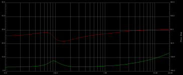
I have now finished building the aperiodic enclosures and have taken an initial impedance sweep with the vent filled with absorbent material. Attached is the impedance which is near enough identical to the vent completely open with no absorbent material. I think I need to increase vent filling density if I am to see any change in the impedance but as the output from the vent is already attenuated a lot compared with an open vent I'm wondering if there's much need for this.
The enclosure is around 28L, has four 5.25" woofers in a 2.5-way MMTMM arrangement. Total vent area for each enclosure is around 10 square inches.
I half expected to see a double peak with the vent open, but this didn't happen.
The enclosure is around 28L, has four 5.25" woofers in a 2.5-way MMTMM arrangement. Total vent area for each enclosure is around 10 square inches.
I half expected to see a double peak with the vent open, but this didn't happen.
Attachments
- Status
- This old topic is closed. If you want to reopen this topic, contact a moderator using the "Report Post" button.
- Home
- Loudspeakers
- Multi-Way
- tuning aperiodic vents