If that impedance is a box with a hole in it (but an aperiodic “filter” over it), then it is either working pretty well as you have completely suppressed the 2nd peak or you may have too much filter and you have effectively sealed the box.
I have found that a filter at the terminus (ie VarioVent/Dyna A25 style) is harder to tune than more distributed damping (or a combo).
This is an aperidoically damped midTL. Free Air vrs in the box impedance. The impedance peaks are dramatically suppressed but you can still see a ghost of the bottom hump. Further refinement flattens it even more.
dave
The vent is 12mm thick and uses three compressed layers of 10mm thick dacron/polyester (as used in upholstery). Between each of those layers is a layer of fine-weave membrane as used for weed suppression among other things. The latter resists air flow quite noticeably when I blow through it, more so than the polyester. I've used gutter mesh to press it all together.
Soundwise the bass sounds OK to me (and it measures broadly in line with my aperiodic simulations) but as the design starts rolling off around 100Hz and the crossover isn't installed yet it'll be a few more days until I can assess it properly subjectively so for the moment my thinking is to leave further vent adjustments until then, particularly as the vent already seems to be attenuating it's own output quite effectively.
Soundwise the bass sounds OK to me (and it measures broadly in line with my aperiodic simulations) but as the design starts rolling off around 100Hz and the crossover isn't installed yet it'll be a few more days until I can assess it properly subjectively so for the moment my thinking is to leave further vent adjustments until then, particularly as the vent already seems to be attenuating it's own output quite effectively.
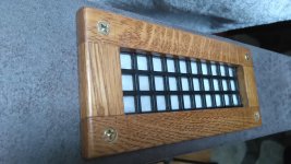
Thanks for your description and photos of your vent - it all seems good on paper!This is the vent...
Dave's impedance plot shows the typical aperiodic action of reducing the amplitude (Q) of the impedance peak while shifting it upwards in frequency.
Your impedance plot shows a small Q impedance peak at a frequency of around 95Hz.
This frequency is rather high for adequate bass reproduction. It would be interesting to know what the free air resonance of your 5.25" drivers is.
You say the impedance curve with the vents open is 'near enough identical' which is a rather puzzling. How does the sound compare with the vents open?
but even with the vent completely open the impedance plot is the same albeit with a marginally lower peak
Then i have to suspect your measurin kit, or that the box is as decided. You put a hole in thebox you should have a 2nd peak.
dave
Many thanks for the replies. I will remeasure soon both with and without vent membrane.
The drive units have an Fs around 67Hz when broken in but the measurements here use non broken in units with a higher Fs around 80Hz IIRC. Low bass extension is not required from this design as subwoofers will supply that.
The drive units have an Fs around 67Hz when broken in but the measurements here use non broken in units with a higher Fs around 80Hz IIRC. Low bass extension is not required from this design as subwoofers will supply that.
Thanks for that info' which is in accord with the aperiodic peak at 95Hz.. . . the measurements here use non broken in units with a higher Fs around 80Hz IIRC.
P.S. Is this is the first time you've mentioned you'll be using a subwoofer? If I'd twigged that I wouldn't have queried the bass extension.
")
....I would have remeasured the impedance by now but I'm enjoying listening to these too much. The bass is really good. Initially I felt it wasn't great but the drivers have been unused since manufacturer in 1998 and perhaps needed some break in. After a few hours the bass sounded very natural and the speakers present a refined and effortless sound. I'll get round to the measurements eventually but in the meantime thanks to everyone for their helpful responses.
Attachments
Thanks Tim.
It takes a wee while to readjust to the lack of 'in your face bass' of an aperiodic cabinet, but soon you begin to revel in its naturalness and excellent transient response. Enjoy!
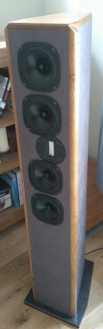
Tim A, I am very interested in what you are trying to do and wish you the best. As Galu said, the whole idea of an aperiodic enclosure is a natural, well controlled bass going into the lower octave. With 4 5.5" woofer, you have the equivalent of a 10" woofer which should allow you to get useful response to about 40 Hz or lower. Below is my experience with aperiodic enclosure using 2 7" woofers.The vent is 12mm thick and uses three compressed layers of 10mm thick dacron/polyester (as used in upholstery). Between each of those layers is a layer of fine-weave membrane as used for weed suppression among other things. The latter resists air flow quite noticeably when I blow through it, more so than the polyester. I've used gutter mesh to press it all together.
Soundwise the bass sounds OK to me (and it measures broadly in line with my aperiodic simulations) but as the design starts rolling off around 100Hz and the crossover isn't installed yet it'll be a few more days until I can assess it properly subjectively so for the moment my thinking is to leave further vent adjustments until then, particularly as the vent already seems to be attenuating it's own output quite effectively.
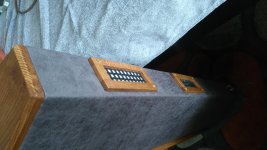
I was always a big fan of the TDL Studio 3 monitor, which was impossible to find in the US and shipping from UK is prohibitively expensive. A few years ago, I ran into some “Wharfedale M-138 Transmission Line Monitor” from Wharfedale in China (Pic 1). I bought them out of curiosity and found that they were the TDL knock-offs. They have the same aperiodic cabinet design (not TL) as the TDL (Pic 2) and a 2nd order crossover. The cabinet was very well built, but the drivers were very poor quality. I started a mod project.


(1) I replaced the drivers with a pair of Peerless 850460 woofers and a Seas 22TAF/G ¾” Aluminuim/magnesium dome. (It mistakenly said Seas 22TFF soft dome in the crossover schematic.)
(2) I modified the cabinet by lining it with 3M 08840 Sound Deadening Pads and replaced the polyester wadding with long fiber wool. The flow resistance plug (foam) is the original.
(3) I modified the crossover to 3rd order and added a zobel network for the woofers. (Pic 3) I was able to keep the circuit board and bi-amp input panel. (Pic 4)


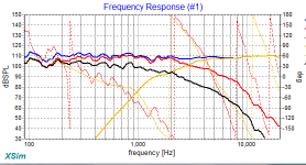
Crossover mod was supported by Jeff Bayby’s PCD software which worked beautifully. The simulation result is shown in Pic 5. I kept the woofer bump to get a bass -6dB cut-off at 35 Hz. It worked exactly as expected. After I fine tuned the driver balance by ears, I made in-site measurement using Ivo Mateljan’s ARTA software. The dip at 450 Hz and the treble drop-off are room effect because I did not make the effort to measure outdoor. (Pic 6) Otherwise, it matches the PCD prediction extremely well.


It is one of the most space and cost effective investment in bass sound I made. The tightness of the bass and its transient response is amazing in listening test.
I later modified 2 more of this enclosure without the tweeter which are used as the twin subwoofers in my main system.
Last edited:
Keilau
Is your last graph the correlation between predicted and measured? I am also a fan of multiple subwoofers and I had two like you, then doubled up to four where I have them in the four corners of the room fed with a mono signal. Room modes almost disappeared when I did that. I might see if I can convert them to aperiodic loading one day.
You mentioned four 5.25" drivers equating to a 10" and this is one of the reasons I opted for a 2.5 way instead of a 3 way design. The Seas drive units here are OEM (I think probably to Proac in their Studio 150) where they are reflex loaded and therefore go much lower in bass. My aim was minimum cone excursion and best transient performance with subwoofers for anything below 100Hz. I find it interesting that even though this is my first aperiodic design, first 2.5-way and first d'appolito design it is also the first design which has emerged exactly as I imagined (hoped) it would sound without any need to fine tune by ear. Funny how these things work! Without Xsim it would have been very different, I'm sure.
- Status
- This old topic is closed. If you want to reopen this topic, contact a moderator using the "Report Post" button.
- Home
- Loudspeakers
- Multi-Way
- tuning aperiodic vents