Hi
Can anyone give me some advice to a box tuning problem please?
I am building some MTM home theatre speakers using Vifa m13sg-09-16 drivers. I'm trying to put them into 14.5 ltr boxes and want to tune the box to 75hz. I have some 70mm Id ports and the port calcs I get should make the length about 85mm. The problem is if I use this it tunes the box a lot lower. I ended up pulling the port out so I was just left with a hole 80mm dia. and 36 mm deep and still the box is only tuned to 66hz. I have double checked volumes ,calcs and everything I can think of multiple times. What am I missing?
Thanks
I had this problem once with a MTM. Sometimes you can get problems with two drivers sharing a volume, especially if there is a high degree of symmetry. You can get unlucky and put the port in a node where the pressure waves from the two woofers cancel, similar to a standing wave. The port doesn't "see" the box. If you are confident your maths is OK, the port dia does look quite big to me, try moving the port location.
Simon
Simon
Hi,
My suggestion is to close the box if you are using two drivers in a 14.5 L box (Qtc=0.718,f-3dB=96Hz)) as the driver Qts is 0.441 and in case of a fairly flat FR ported box you need at least 34 L tuned to 50 Hz (Qt= 0.577,f-3dB about 43 Hz).
b
1(1)
My suggestion is to close the box if you are using two drivers in a 14.5 L box (Qtc=0.718,f-3dB=96Hz)) as the driver Qts is 0.441 and in case of a fairly flat FR ported box you need at least 34 L tuned to 50 Hz (Qt= 0.577,f-3dB about 43 Hz).
b
1(1)
Attachments
Hi,
Shown for two drivers in a box, with specs from here :
http://www.speakerbits.com/net/catalogs/showpic1.aspx?id=VF130B
") /sreten.
/sreten.
Shown for two drivers in a box, with specs from here :
http://www.speakerbits.com/net/catalogs/showpic1.aspx?id=VF130B
/sreten.Attachments
Hi and thanks everyone for their input.
I'm now confused by your post bjorno. 34l
I am new to speaker design but have modeled the drivers in 3 different software packages, multiple times, and with a slight variance always come up with 12 - 16 L depending on alignments. Would it be normal for 2 X 5.5 inch drivers to require 34L? Or am I doing something wrong?
Thanks sreten that model looks more in line with what I am getting. Yes?
Thanks Simon, I think I will try moving the port. There is a shelf brace a little near the port. Could this be interfering?
bjorno said:Hi,
My suggestion is to close the box if you are using two drivers in a 14.5 L box (Qtc=0.718,f-3dB=96Hz)) as the driver Qts is 0.441 and in case of a fairly flat FR ported box you need at least 34 L tuned to 50 Hz (Qt= 0.577,f-3dB about 43 Hz).
b
1(1)
I'm now confused by your post bjorno. 34l
I am new to speaker design but have modeled the drivers in 3 different software packages, multiple times, and with a slight variance always come up with 12 - 16 L depending on alignments. Would it be normal for 2 X 5.5 inch drivers to require 34L? Or am I doing something wrong?
Thanks sreten that model looks more in line with what I am getting. Yes?
Thanks Simon, I think I will try moving the port. There is a shelf brace a little near the port. Could this be interfering?
…I'm now confused by your post bjorno. 34l…
Entering simple data in a simulation program that only relies on data like Qts, Vas and fs is can lead to a design disaster if not previously checking the data consistency.
b
1(1)
Attachments
There is a shelf brace a little near the port. Could this be interfering?
Possibly, if any surface is close enough to the port it will alter the efectiveness of the port a little or a lot, it is hard to predict! Avoid symmetry is my advice.
Simon
Brownee said:Hi
Can anyone give me some advice to a box tuning problem please?
I am building some MTM home theatre speakers using Vifa m13sg-09-16 drivers. I'm trying to put them into 14.5 ltr boxes and want to tune the box to 75hz. I have some 70mm Id ports and the port calcs I get should make the length about 85mm. The problem is if I use this it tunes the box a lot lower. I ended up pulling the port out so I was just left with a hole 80mm dia. and 36 mm deep and still the box is only tuned to 66hz. I have double checked volumes ,calcs and everything I can think of multiple times. What am I missing?
Thanks
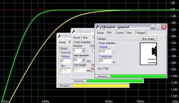
Yes, an empty box of 14,5 litres total volume, 70 mm vent diameter, would need a tube length of 81 mm if it is to be tuned to 75 Hz. If the box is filled completely with ideally isothermalizing material, the vent length should be 41 mm. A more realistic amount of box stuffing, corresponding to 40% fill of ideally isothermalizing material results in a port length of 62 mm.
So, this does not explain why you measure 66 Hz with 36 mm port length. So I'll have to look for other things.
How certain are you of the box volume? Is it for both drivers, or is it per driver, ie total 29 litres?
How do you measure the port resonance? Through the impedance curve? Do you connect both drivers doing this, or only one? Both should be connected, in series or parallel does not matter. If it is a 2.5 system bypass the crossover for this measurement, since it feeds slightly different signals to the drivers.
HTH
Hi Svante
.
The box has 1" of R19 fiberglass on all walls except baffle.
I have checked and re-checked the box volume (doesn't mean it's right though ). The volume is for two drivers, not each. The box internal dimensions are 580 X 139 X 183 which gives 14.75L. Because the baffle is 36mm thick only the driver magnets protrude into the volume and because the holes have a large 22 degree bevel I work out that they don’t take any volume at all.
That leaves the port and small brace to take up .25L.
I used an impedance curve. I have a "Woofer Tester 2" http://www.woofertester.com/wt2product.htm
Both drivers are connected in parallel, no crossover. I ran a sweep and located the min Z between the two peaks. I also checked by placing a sound meter close to a driver and used a sine generator to get the min output freq. Also the Woofer Tester has a measure box feature that gives Fb and box size. All match up
.
If the box is filled completely with ideally isothermalizing material, the vent length should be 41 mm. A more realistic amount of box stuffing, corresponding to 40% fill of ideally isothermalizing material results in a port length of 62 mm.
The box has 1" of R19 fiberglass on all walls except baffle.
How certain are you of the box volume? Is it for both drivers, or is it per driver, ie total 29 litres?
I have checked and re-checked the box volume (doesn't mean it's right though
). The volume is for two drivers, not each. The box internal dimensions are 580 X 139 X 183 which gives 14.75L. Because the baffle is 36mm thick only the driver magnets protrude into the volume and because the holes have a large 22 degree bevel I work out that they don’t take any volume at all.That leaves the port and small brace to take up .25L.
How do you measure the port resonance? Through the impedance curve? Do you connect both drivers doing this, or only one? Both should be connected, in series or parallel does not matter
I used an impedance curve. I have a "Woofer Tester 2" http://www.woofertester.com/wt2product.htm
Both drivers are connected in parallel, no crossover. I ran a sweep and located the min Z between the two peaks. I also checked by placing a sound meter close to a driver and used a sine generator to get the min output freq. Also the Woofer Tester has a measure box feature that gives Fb and box size. All match up
Hi,
I believe you still are using a too small box for the two Vifa’s M13SG-09-16 and the TS input data to calculate your box is supplied by a careless driver retailer that just copied and transferred some data from the M13SG-09-08 drivers to the 16 Ohm version.
Here is another similar M-T-M design using an internal volume of 0.58 cu. ft.:
http://www.lungster.com/l/speakers/mtmcenter/mtmcenter.shtml:
////…As luck would have it, Madisound has a Vifa kit utilizing two M13SG-09-16 and one D25ASG-05. The kit can be purchased complete with all parts and cabinet or as individual pieces. Since I wanted to build the box to suit my taste and decor, I bought the woofers and crossover (I already had the tweeter). Incidentally, the M13SG-09 comes in both an 8 ohm version (-08 suffix) and 16 ohm version (-16 suffix). The 16 ohm version allows two such drivers in parallel to yield an 8 ohm nominal impedance.
The claimed response by Madisound is 40 Hz to 35 KHz vented and 80 Hz to 35 KHz sealed. My own calculations yielded an F3 of above 100 Hz in a sealed cabinet… of 0.58 cu. ft…////
…using the drivers from:
http://www.madisound.com/catalog/PDF/vifa/M13SG09-16.pdf
See the simulation using the more trustworthy Madisound TS data of Vifa M13SG-09-16 in a closed 0.58 cu. ft. box: 1(2)-2(2)
b
1(2)
Attachments
Simming it on Unibox, for a 14.5l box, using ONE 70mm port, I get that you need a 20cm length to get 73Hz f3 (tuning is at 54Hz).
14.5l box, ONE 8.5cm port, gives tuning at 75Hz, f3 of 70, but a 2dB+ peak at about 115Hz
And as someone said earlier, in a sealed box, you'll get an f3 of around 100Hz.
In any of these boxes, feed it more than 15W at 90Hz or below and you're going to get close to Xpeak (more than 150% Xmax). Worse in a larger box. I'd be tempted to actively cross then at about 120Hz in a sealed box to a larger woofer box for each unit.
I believe you still are using a too small box for the two Vifa’s M13SG-09-16 and the TS input data to calculate your box is supplied by a careless driver retailer that just copied and transferred some data from the M13SG-09-08 drivers to the 16 Ohm version.
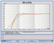
Thanks bjorno, I measured the T/S parameters of the actual drivers I am using. I rechecked them today. I measured two impedance sweeps (free air and delta mass) and then imported them into LEAP Enclosure Shop. I then used its Transducer Modeling feature to get the T/S params on all the drivers.(see text file) I then used these to model the enclosure in Enclosure shop. See Attachment
The 16L sealed sim is smooth but I don't think it extends enough.
The 16L verses the 14.5 ported options seem very close. I can alter the boxes to get the 16 but is it worth it ? Are the ported curves acceptable or am I missing something?
In any of these boxes, feed it more than 15W at 90Hz or below and you're going to get close to Xpeak (more than 150% Xmax). Worse in a larger box. I'd be tempted to actively cross then at about 120Hz in a sealed box to a larger woofer box for each unit
This project is for home theater and my amp can be set to filter below 80 or 100hz so this is less of a problem. I have a sub to fill in the bottom end.
Attachments
…The 16L verses the 14.5 ported options seem very close. I can alter the boxes to get the 16 but is it worth it ? Are the ported curves acceptable or am I missing something…
Hi Browniee,
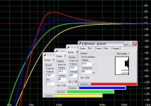
Your new data makes a difference; I need more time to investigate and will soon return with a simulation using the average data of your drivers. I don’t think the difference between 14.5-16L is of greater importance, as the difference is only about 10%.
The ported curves seem quite plausible but the peaking about an dB can be tamed by putting damping materials in the ports.
Meanwhile, take a look at the submitted simulations showing the possibility to turn your ported boxes into aperiodic types, i.e. damped box, damped port. 1(1)-2(2)
b
1(2)
Attachments
Thanks bjorno
I’m not familiar with this type of enclosure. I will have to look into it.
Meanwhile, take a look at the submitted simulations showing the possibility to turn your ported boxes into aperiodic types, i.e. damped box, damped port. 1(1)-2(2)
I’m not familiar with this type of enclosure. I will have to look into it.
Brownee said:Hi Svante
.
The box has 1" of R19 fiberglass on all walls except baffle.
I have checked and re-checked the box volume (doesn't mean it's right though
That leaves the port and small brace to take up .25L.
I used an impedance curve. I have a "Woofer Tester 2" http://www.woofertester.com/wt2product.htm
Both drivers are connected in parallel, no crossover. I ran a sweep and located the min Z between the two peaks. I also checked by placing a sound meter close to a driver and used a sine generator to get the min output freq. Also the Woofer Tester has a measure box feature that gives Fb and box size. All match up
Ok, seems all ok to me. Is it possible to remove the stuffing, just to check what happens with the resonance frequency then?
Also, is it possible to use an alternate sampling frequency in the software? Sometimes soundcards gets confused about what sampling rate it is really using. This results in a shift in all measured frequencues. I have one at work that sometimes runs at 48000 Hz even though I tell it to run at 44100 Hz. If possible you could also try a completely different soundcard or computer.
- Status
- This old topic is closed. If you want to reopen this topic, contact a moderator using the "Report Post" button.
- Home
- Loudspeakers
- Multi-Way
- What’s going on with my port tuning?