I'm looking to build a spreadsheet into which I can enter speaker SPL and phase and then inductor and capacitor values for given crossover networks and get a summed output. To do this I need the formulae for the effects of inductors and capacitors on signals but I can't seem to find this basic stuff. Could anyone point me in the right direction?
Am just looking to do 2nd order 2-way crossovers initially but presumably once you know the sums then one can extrapolate from there.
Thanks!
Alex
Am just looking to do 2nd order 2-way crossovers initially but presumably once you know the sums then one can extrapolate from there.
Thanks!
Alex
Look for Jeff Bagby's Passive Crossover Designer. It does what you want without needing to know the formulas.
Someone could give you the formulas, but they would have to type it all out.... and then not know if you even know how to use them. In my mind, if you knew how to use them, you could derive them yourself.
Someone could give you the formulas, but they would have to type it all out.... and then not know if you even know how to use them. In my mind, if you knew how to use them, you could derive them yourself.
Ron E said:Look for Jeff Bagby's Passive Crossover Designer. It does what you want without needing to know the formulas.
Someone could give you the formulas, but they would have to type it all out.... and then not know if you even know how to use them. In my mind, if you knew how to use them, you could derive them yourself.
Thanks, have downloaded that. I do have a fair understanding of how this stuff works, I guess my engineering degree is finally proving useful. If I knew how to use them completely then I probably could derive them, however I am learning the fine details of all this and thus would need more info before I could work back from first principles.
Alex
Draw the schematic, replace the capacitors with a resistor with resistance 1/(j 2 pi f C) (j is sqrt(-1), f is frequency, and C is the original capacitance), and the inductors with (j 2 pi f L). Then, treat the crossover like a normal resistor network, and derive a symbolic (function of f) transfer function.alexclaber said:I'm looking to build a spreadsheet into which I can enter speaker SPL and phase and then inductor and capacitor values for given crossover networks and get a summed output. To do this I need the formulae for the effects of inductors and capacitors on signals but I can't seem to find this basic stuff. Could anyone point me in the right direction?
Plot the magnitude of that function versus f for the magnitude response, and the phase versus f for the phase response. This approach is accurate and easy - if you aren't afraid of complex numbers.
")
If you're going to draw a schematic, you might as well draw it in LTspice (free from linear.com) and have the entire magnitude and phase response plotted automatically.
You will probably want to remember to include the parasitic series resistances of inductors and capacitors.
You will probably want to remember to include the parasitic series resistances of inductors and capacitors.
Have been messing with LTspice and also working on an excel spreadsheet. Suffice to say that my brain is melting...
Whilst I get my head round all that I've designed a simple 2nd order Butterworth crossover @ 750Hz (as this bass cab will rarely be on-axis I felt the flatter power response was more important than on-axis response). Have used the actual impedance at that point, not nominal impedance for the component calculation.
Hopefully as the impedance stays +50%/-20% an octave either side of the crossover point, the filter response won't be too far from theoretical?
Alex
Here is how to do a 2nd order lowpass to get you started
An externally hosted image should be here but it was not working when we last tested it.
Thanks!
Can I just clarify a couple of things on there?
U0/U1 is the transfer function.
R is the resistance of the inductor.
|U0/U1| is the magnitude of the transfer function.
To calculate how the woofer and midrange combine acoustically, I presume I also need the argument (phase) of the transfer function?
Alex
alexclaber said:Thanks!
Can I just clarify a couple of things on there?
U0/U1 is the transfer function.
Yes, it is the ratio between the output voltage u0 and the input voltage u1, as in the circuit diagram.
alexclaber said:
R is the resistance of the inductor.
No, the inductor is ideal. R is the load resistance. Simplified, it can be seen as the loudspeaker, but mostly that is an oversimplification that gives rather large errors.
alexclaber said:
|U0/U1| is the magnitude of the transfer function.
Yes.
alexclaber said:
To calculate how the woofer and midrange combine acoustically, I presume I also need the argument (phase) of the transfer function?
Alex
The phase is present in the u0/u1 equation, there is a "j" in there which makes the expression a complex number. Complex numbers have a magnitude and a phase, and I derived the magitude from that, only.
However, it messes things up if you start to split the equation into magnitude and phase and try to add them afterwards. It is better to just add the two complex transfer functions.
Are you familiar with complex numbers and the jw-metod?
Hi,
Why are you doing this ? It may save time making a set of purely
theoretical calculations. The reality is real crossovers done properly
bear little resemble to any simplistic approach, which this is.
You can go on line to easily find the simplistic (and wrong) values.
http://www.mhsoft.nl/CrossoverNetworksForLoudspeakers.asp
/sreten.
Why are you doing this ? It may save time making a set of purely
theoretical calculations. The reality is real crossovers done properly
bear little resemble to any simplistic approach, which this is.
You can go on line to easily find the simplistic (and wrong) values.
http://www.mhsoft.nl/CrossoverNetworksForLoudspeakers.asp
/sreten.Svante said:No, the inductor is ideal. R is the load resistance. Simplified, it can be seen as the loudspeaker, but mostly that is an oversimplification that gives rather large errors.
That's what was bothering me - the loudspeaker is a load of variable impedance.
Svante said:The phase is present in the u0/u1 equation, there is a "j" in there which makes the expression a complex number. Complex numbers have a magnitude and a phase, and I derived the magitude from that, only.
Yes, I saw that. Would I be incorrect to presume that one could apply the transfer function to each speaker, then figure in the unfiltered response (including phase) of the speaker and then add the resulting complex numbers for each frequency band to get the resulting acoustic output?
Svante said:Are you familiar with complex numbers and the jw-metod?
I'm familiar though rusty with complex numbers. The jw method I starting learning about a couple of days ago.
sreten said:Why are you doing this ? It may save time making a set of purely
theoretical calculations. The reality is real crossovers done properly
bear little resemble to any simplistic approach, which this is.
My aim is to both develop a better understanding of crossover design and also to find a way to get a relatively simple crossover network to perform as I need for a 2-way woofer+midrange bass guitar cab, without having to use expensive and complex impedance compensation components. If you were in my shoes, what would your approach be?
Alex
sreten said:Hi,
Why are you doing this ? It may save time making a set of purely
theoretical calculations. The reality is real crossovers done properly
bear little resemble to any simplistic approach, which this is.
You can go on line to easily find the simplistic (and wrong) values.
http://www.mhsoft.nl/CrossoverNetworksForLoudspeakers.asp
I think this is pure education, to understand the fundaments of crossover filters.
Going to a web page to get set of values does not contribute to understanding in the same way.
I otherwise agree that since the load (which is more complex than my "R" in the above calculations) and response of the drivers will require other values for the filter components than this exercise will show.
For real filters, simulations that include driver impedances and responses should be used.
...now I answered a question that was not put to me, my bad...
alexclaber said:
Yes, I saw that. Would I be incorrect to presume that one could apply the transfer function to each speaker, then figure in the unfiltered response (including phase) of the speaker and then add the resulting complex numbers for each frequency band to get the resulting acoustic output?
You would have to replace the R with the actual complex (magnitude/phase) of the drivers too, but if you do that, the predictions will be very accurate. Given the rather complicated nature of the loudspeaker impedance, this is hardly something you do with pen and paper, it is better to simulate it.
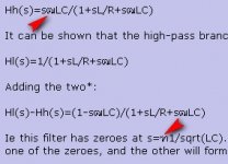
Ok, so let's do the theoretical addition of the two branches of a 2nd order filter. As I showed above, the HP# filter is:
Hh(s)=s²LC/(1+sL/R+s²LC)
It can be shown that the high-pass branch is:
Hl(s)=1/(1+sL/R+s²LC)
Adding the two*:
Hl(s)-Hh(s)=(1-s²LC)/(1+sL/R+s²LC)
Ie this filter has zeroes at s=±1/sqrt(LC). If both poles are located at s=-1/sqrt(LC), one of them will cancel one of the zeroes, and the other will form an all-pass filter together with the remaining zero at s=+1/sqrt(LC).
*Phase has to be shifted in one of the drivers for a 2nd order filter
#I incorrectly wrote that it was a LP filter above, of course it is the HP section i drew.
Svante said:You would have to replace the R with the actual complex (magnitude/phase) of the drivers too, but if you do that, the predictions will be very accurate. Given the rather complicated nature of the loudspeaker impedance, this is hardly something you do with pen and paper, it is better to simulate it.
Having used WinISD Pro for low frequency simulations and all impedance data, plus the manufacturer's plot for higher frequency response, I do now have a spreadsheet with all that data in. So I could then add columns which calculate the filter response at each data point, and then have a plot automatically created of the total response. Then experiment with different crossover component values to see how I can tweak the response. Does that seem logical?
Alex
...Does that seem logical?..
Yes, but for the total summed acoustic response (For this case only coincidence drivers will be valid), only if the driver magnitude (dB) is added to the magnitude of filter attenuation (dB) and the phase of the driver is summed with the filter phase too.
FYI, Complementing the picture of the high pass filter derivation in post# 7 with a low pass filter ditto, tested step by step on my son for the evaluation of the ‘clarity’ as he just learnt complex number algebra.
b
1(1)
...Does that seem logical?..
Attachments

bjorno said:
FYI, Complementing the picture of the high pass filter derivation in post# 7 with a low pass filter ditto, tested step by step on my son for the evaluation of the ‘clarity’ as he just learnt complex number algebra.
Nice! I think there is a small mistake in the attached image, though; it says uin/uout instead of uout/uin, right?
Nice! I think there is a small mistake in the attached image, though; it says uin/uout instead of uout/uin, right?
Right, Thank you Svante !
b
1(1)
Attachments
alexclaber said:
My aim is to both develop a better understanding of crossover design and also to find a way to get a relatively simple crossover network to perform as I need for a 2-way woofer+midrange bass guitar cab, without having to use expensive and complex impedance compensation components.
If you were in my shoes, what would your approach be?
Alex
Hi,
It completely depends on the drivers in question, noting that hi-fi
2-way design has little to do with bass guitar cabinets. You are
absolutely right in that compensation networks are a waste of
time for a bass guitar rig, pretty much true for PA speakers also.
Theory will get you absolutely nowhere other than the wrong
answer unless you use a fully detailed simulation. All other
"simplifications" are wrong by the degree of simplification.
FWIW a 15" bass driver + 8" sealed back midrange, given typical
parameters the crossover is usually only a high pass to the
midrange, the 15" used fullrange. Same for 15" + horn tweeter.
/sreten.hi svente
i don't know what the words that you type. now i'm thinking that you type it for the people in another worlds.lol
hi brighton guy
plese you type the full words for me to understand.
FWIW=?
and answer a litle.
i.e=? i only know internet explorer.
WBT=? i only know the BMW(car)lol
i don't know what the words that you type. now i'm thinking that you type it for the people in another worlds.lol
hi brighton guy
plese you type the full words for me to understand.
FWIW=?
and answer a litle.
i.e=? i only know internet explorer.
WBT=? i only know the BMW(car)lol
Attachments
- Status
- This old topic is closed. If you want to reopen this topic, contact a moderator using the "Report Post" button.
- Home
- Loudspeakers
- Multi-Way
- Formulae for calculating crossover magnitude and phase based on component values