Re-Jigging the jig: Speaker testing device for Arta, Speaker Workshop & HOLMImpulse
About 3 years ago I started to seriously research speaker design and building. I had always built speakers, but that was by guess only. None of my "designs" had any science behind them.
I found Speaker Workshop, and decided I'd use that to help my new designs. I ordered the parts for a Wallin jig and set about building it. It took hours to build this and when it was done, it didn't work! I spent several more hours tracking down the cause of the problem.
Now, I'm in no way putting down Eric Wallin's design, but for what it does, it's too complicated. Trying to squish all of those switches and resistors and wires into that little project box is tough.
Originally, I only used SW for driver impedance testing, to determine the T/S parameters. Later, I decided I'd try to use it for frequency response testing, so I ordered the parts to build Wallins mic preamp. That was fine: I now had a preamp, a homemade mic and the test jig. I needed an amp. The only thing I had (at the time) was a vintage Pioneer SA-6800 - big and bulky.
This kind of setup in ok if you have a dedicated space, where you can leave everything connected and undisturbed. If you need to move things, then the setup doesn't seem so good.
With this in mind, about a year ago, I changed things. I rebuilt the jig on a circuit board and included the mic preamp. I then built an amp with an LM3886 chip amp. I packed all of this into an empty computer power supply housing. I had the power supply for the chip amp on a piece of plywood, sitting next to the new jig.
This setup was better, and I have been using it up till now. The only drawback is the separate power supply.
I thought it would be nice to have everything in one neat and tidy package. Something that was well designed and included all of the important features.
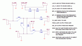
I started with the jig itself. I made some changes that, to me, made sense. I eliminated the 4/16 ohm calibration resistors and with it the switch that puts these in and out of the circuit. I also deleted the clamping zeners as these are a potential source for distortion.
I established a voltage divider for the amplified signal which will protect the sound card from the amp.
I made the switches more "friendly", with just 2 on the front panel for jig function: direct SW3 (puts the jig in loop back for sound card calibration) and frequency response/impedance measure SW1.
The power switch for the amp (SW2) also cuts the line out from line in, allowing all of the connection cables between the jig and the sound card to remain in place.
About 3 years ago I started to seriously research speaker design and building. I had always built speakers, but that was by guess only. None of my "designs" had any science behind them.
I found Speaker Workshop, and decided I'd use that to help my new designs. I ordered the parts for a Wallin jig and set about building it. It took hours to build this and when it was done, it didn't work! I spent several more hours tracking down the cause of the problem.
Now, I'm in no way putting down Eric Wallin's design, but for what it does, it's too complicated. Trying to squish all of those switches and resistors and wires into that little project box is tough.
Originally, I only used SW for driver impedance testing, to determine the T/S parameters. Later, I decided I'd try to use it for frequency response testing, so I ordered the parts to build Wallins mic preamp. That was fine: I now had a preamp, a homemade mic and the test jig. I needed an amp. The only thing I had (at the time) was a vintage Pioneer SA-6800 - big and bulky.
This kind of setup in ok if you have a dedicated space, where you can leave everything connected and undisturbed. If you need to move things, then the setup doesn't seem so good.
With this in mind, about a year ago, I changed things. I rebuilt the jig on a circuit board and included the mic preamp. I then built an amp with an LM3886 chip amp. I packed all of this into an empty computer power supply housing. I had the power supply for the chip amp on a piece of plywood, sitting next to the new jig.
This setup was better, and I have been using it up till now. The only drawback is the separate power supply.
I thought it would be nice to have everything in one neat and tidy package. Something that was well designed and included all of the important features.
I started with the jig itself. I made some changes that, to me, made sense. I eliminated the 4/16 ohm calibration resistors and with it the switch that puts these in and out of the circuit. I also deleted the clamping zeners as these are a potential source for distortion.
I established a voltage divider for the amplified signal which will protect the sound card from the amp.
I made the switches more "friendly", with just 2 on the front panel for jig function: direct SW3 (puts the jig in loop back for sound card calibration) and frequency response/impedance measure SW1.
The power switch for the amp (SW2) also cuts the line out from line in, allowing all of the connection cables between the jig and the sound card to remain in place.
Attachments
gootee said:That sounds like a good little unit, John! I wish I had one. Do you have any photos?
Hi Tom,
Yes, I've got some pictures of my progress so far, and I'll be posting those as I go along. As it is not fully complete, I'd appreciate any comments for improvement, especially with the jig circuit above.
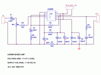
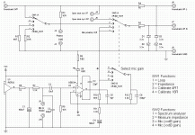
I wanted to make the amp for frequency response testing as compact and simple as possible. I used the same circuit design I've used for other chip amps I've built, but I reduced the supply voltage to +/-18 V and reduced the gain to 11 V/V. Typically, this amp will only supply a watt or two in most instances.
By keeping the supply voltage low, I could use smaller 25 V electrolytic, making the board layout as compact as possible. Making the board double sided, I created pads on the top copper and on the bottom copper to surface mount the leads of the LM3886, rather than thru hole mounting. This allows for wider traces in a more compact layout.
Here's the schematic for the amp:
Attachments
pinkmouse said:I'm building something not dissimilar, only I'm keeping the mic pre separate.
That is very professional looking Al. How much more work do you need to do on it? What did you use for the front panel labeling?
On mine, I tried to use the laser print transfer method, but it kind of smeared (I'll post a pic later).
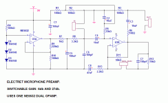
For the mic preamp, I used Eric Wallin's design, but made some changes. Having built the preamp before, I know how well it works - low noise and efficient. A 9 volt battery lasts a long time.
I used the NE5532 for the opamp. This opamp is as good as they get IMO.
No major changes to the circuit, other than eliminating the clipping indicator. Test that I made during the construction of this preamp show clipping to be well above the practical input level.
In the original design, the gain is selectable between 2 and 20. I found the low gain useless - I never used it as the output was not enough. Likewise, the high gain seems just adequate sometimes so I went ahead and changed that, increasing the gain to ~7 and 27 for low and high.
Attachments
John, it is indeed toner transfer. The secret with front panels is to scuff them up a bit so the toner adheres. I just ran an orbital sander loaded with 150 grit over it lightly 'till I got an even look. As for completion, I'm working on it as we speak, just waiting for the chipamp board to etch at the moment. I hope to be finished by close of play today, then some testing tomorrow. ")
My mic pre is the kit that Vikash sells, AFAIK, it's not disimilar to the Wallin one
My mic pre is the kit that Vikash sells, AFAIK, it's not disimilar to the Wallin one
pinkmouse said:John, it is indeed toner transfer.
Hi Al,
My trouble started when I tried to print the labels in a mirror image. For some stupid reason, my printer (HP 3050) software doesn't support it, so I had to improvise. I used MS Word to type the words on the screen, then did a screen capture to the clipboard. Pasted this to Paint and reverse and resized the type.
A genuine pain in the ****.
There must be a better way.
Then, the front panel on mine is solid white oak. I sanded this as smooth as I could get it, but it still has open grain.
I can't say I'm thrilled with the results, but it's good enough for what it is and as long as I can read it, it'll be fine.
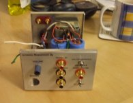
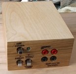
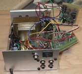
Here's a pic of the final finished product. Overall dimensions are 3" high, 5 1/2" wide and 7 1/2" deep. Jacks for sound card connection, mic input, power mains input and a switch for mic gain are on the back (more pics to come).
This morning I added a "power on" LED for the mic preamp. This will remind me to turn it off
Attachments
Haven't we all been busy!
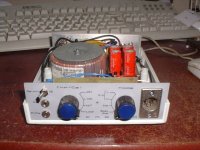
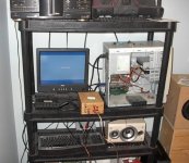
The attached pic is my take on the all-in-one Speaker Workshop jig. It contains an L165V chip amp, my own design mic pre-amp and all the signal switching of the Wallin jig but compressed onto two rotary switches. I've also added a spectrum analyser function for measuring the frequency response of active crossovers and the like.
I'm currently in the process of redesigning the jig - squeezing it into such a small case meant some compromise needed to be made. Swapping the ghastly L165V power op-amp for a LM3886 is on the agenda as is improving signal routing.
Nice one,
David.
Attachments
MJL21193 said:
Hi Tom,
Yes, I've got some pictures of my progress so far, and I'll be posting those as I go along. As it is not fully complete, I'd appreciate any comments for improvement, especially with the jig circuit above.
I wanted to make the amp for frequency response testing as compact and simple as possible. I used the same circuit design I've used for other chip amps I've built, but I reduced the supply voltage to +/-18 V and reduced the gain to 11 V/V. Typically, this amp will only supply a watt or two in most instances.
By keeping the supply voltage low, I could use smaller 25 V electrolytic, making the board layout as compact as possible. Making the board double sided, I created pads on the top copper and on the bottom copper to surface mount the leads of the LM3886, rather than thru hole mounting. This allows for wider traces in a more compact layout.
Here's the schematic for the amp:
This all sounds good.
One thought that just occurred to me: A higher chipamp gain than 11 V/V might give better performance. If so, you could just put a resistive divider before the input, and keep the overall gain wherever you want it.
daatkins said:Haven't we all been busy!
The attached pic is my take on the all-in-one Speaker Workshop jig. It contains an L165V chip amp, my own design mic pre-amp and all the signal switching of the Wallin jig but compressed onto two rotary switches. I've also added a spectrum analyser function for measuring the frequency response of active crossovers and the like.
David.
Hi David,
Very Nice! The rotary switches are the best choice or extra functionality. I should have considered it (next time
).The spectrum analyzer is PC based?
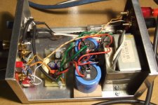
Here is a shot of the guts of mine from behind. The amp, preamp and jig are all on separate boards, connected together via terminal blocks. Makes for a bit of a snakes nest, but gives more flexibility in squeezing everything in.
The LM3886 amp is attached to the bottom aluminum plate, which serves as the heatsink.
Attachments
gootee said:
This all sounds good.
One thought that just occurred to me: A higher chipamp gain than 11 V/V might give better performance. If so, you could just put a resistive divider before the input, and keep the overall gain wherever you want it.
Hi Tom,
I don't think there's a drop in performance with the gain at 11. The minimum (for stability) is 10. I did some squarewave testing on the completed amp (with a 4 ohm coax speaker as load) and it runs beautifully.
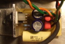
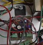
Here's an up close shot of the amp board. notice how the leads from the LM3886 are surface mount on the top and bottom of the board.
Attachments
pinkmouse said:Well, the OPA548 amp module is up and running, (is it small enough I wonder?
pinkmouse said:Ok, time to take it apart again and rewire it properly so the sense resistor actually connects into the speaker line...
Hi Al,
Any specific reason why you used the OPA548? I haven't looked closely at the specs, but it's about $11 from Digikey here, almost twice the cost of the LM3886. I had some spares (with short leads - cut off of my active amp boards), so no cost for me really. How's the performance of the OPA stack up to the LM? Or is it more like my situation - as in "this is what I have"
I'm impressed with the LM3886 though, not only sound quality wise: I etched the board, looked it over then populated it. Looked it over again and fired it up on the +/-18 V supply. It didn't sound right, too low and distorted. It turns out there was a tiny copper bridge from the output to the negative rail.
This abuse
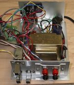
, coupled with the previous abuse I heaped upon it in the active amp board fiasco, tells me these are tough little customers. With that said, I doubt it would have survived a higher rail voltage, say +/-35. I need to break out the old magnifying glass. .A full frontal view, nude. I wanted to make it so that everything was attached to the sub chassis, and the cover would slide on over it all. Complicates construction a bit, but makes it easier to put together and work on in the future. There's an abundance of recycled parts, gleaned from old receivers and other low dollar "finds".
Attachments
Hi John, Al,
I am wondering about one thing. Why make the chassis so small? It makes the pickup of noise from the supply that much more likely. It's also more difficult to add to or service.
I understand that one uses what one has on hand, but wouldn't a case large enough to slide under another item be easier to deal with? Also, it wouldn't tend to skid around when connecting to it.
A nice, flat toroid (can you believe I'm recommending s toroid???) may allow a larger, flatter case. One you could place your laptop on top of and even provide for extra cooling for the laptop. Then you have just saved on bench space on top of this.
Just an option for future.
-Chris
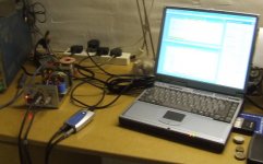
pinkmouse said:And the setup in action:
What sound card are you using? I had an old Thinkpad 780ed that I tried before with an Audigy PCMCIA card, but it wouldn't work - processor wasn't fast enough (PII, 266MHz). I gave up on that and switched to a desktop, but I'm having issues with that too (see below)
anatech said:Hi John, Al,
I am wondering about one thing. Why make the chassis so small? It makes the pickup of noise from the supply that much more likely. It's also more difficult to add to or service.
Hi Chris,
I considered a wider case, but I thought a smaller, narrower one would be neater and more mobile. This would need to be moved every once in a while. Another problem with putting the unit under something else is cable access - if you need to change something, it needs to be moved. This is unless you put everything in the front panel, or use spliced cables for quick removal.
To do it again, I'd make it even smaller - narrower but a little deeper.
As for noise, I used a shielded transformer, grounded to the case. All of the small signal runs are shielded cable. This whole unit, with the mic preamp inside, is ultra quiet, certainly more than quiet enough for the purpose.
I'm now having computer problems. The computer I have been using is an 8 year old P3 1Ghz. Integrated audio has one functional channel, and the Soundblaster card that I originally put in there 6 years ago is burned out (I did it - overloaded it using RMAA to test an amp).
Now the replacement soundcard, Audigy 2 SE, was working ok for a while but with some glitches. Random restarts, BSOD, freeze ups. A driver issue, most likely. I bring the computer up here for internet access (none in my "lab") to find some drivers.
I discover the chipset, Via VT82C686A has an audio problem, that was never resolved by Via. In the installation troubleshooter for the new Audigy, it specifically singles out this chipset.
Long story short, I'm looking for another socket 370 motherboard. I see several on Ebay, a particularly nice on is the Intel D815EEA.
My unit is fully functonal and works like a charm. I had it up here connected to my real computer and everything looks good.
Here's my (not working) lab setup:
Attachments
MJL21193 said:
I'm looking for another socket 370 motherboard. I see several on Ebay, a particularly nice on is the Intel D815EEA.
Hi John,
I hope you are aware that a motherboard with Intel 815 chipset can only address up to 512MB memory. It may not be an issue for you but maybe worth mentioning.
- Status
- This old topic is closed. If you want to reopen this topic, contact a moderator using the "Report Post" button.
- Home
- Loudspeakers
- Multi-Way
- Re-Jigging the jig: Speaker testing device for Arta, Speaker Workshop & HOLMImpulse