Earl,Guys, you have it incorrect. The theory says that there should not be beaming and my data shows that as well. Of course this is only true if you use a precisely correct OS contour with a well handled mouth. Any other approach and there will likely be beaming.
You simply cannot state that "Pancake drivers radiate hf wider." because there is no radiation in all cases.
"High frequency wavefront has not opened up or "bloomed" yet completely" - this is not a scientific statement, but is not actually correct as I would interpret it. The diffraction at the end of a compression river will happen immediately and will splay to the sides and imping on the "injection ports".
After reviewing some data I have to disagree with you on this, though Legis claim of the 15 degree conical horn in the throat of the JBL 24XX series horns affecting dispersion down to 3-4 kHz is stretching by a bit more than an octave. I think Legis initial parabolic expansion coupled to a conical expansion is doing some weird stuff ;^).
That said, the beaming of tractrix/expo etc. horns he mentions has also been pointed out by you on many occaisions.
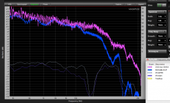
I have a comparison below between a JBL 2420 (1" exit) with the 15 degree horn snout on a 90 x 45 conical horn and a 1.4" exit "pancake" Celestion CDX14-3050 on a 90 x 40 conical, with injection ports. The injection ports have little effect, the deep hole in the response of the driver at 12kHz is there with or without the ports.
Both horns have the throat entrance smoothed. The 45 degree off axis trace has been raised by 6 dB in both cases. The CDX14-3050 (STEQ) was equalized (roughly) flat on axis, the JBL is unequalized.
Though the JBL shows a clear narrowing trend above 10kHz, the pancake driver on axis and 45 degree off axis response are within a dB from 12 to 16 kHz. With the general design of the two horns being the same, the charts clearly exhibit that it is the narrow JBL throat that narrows VHF dispersion.
Art
Attachments
Earl,
The question becomes what is a full wavelength at a 1" diameter?
What difference does that make?
I have thought the whole narrowing radiation pattern of tractrix/expo etc. horns is because of the same phenomenom I was talking about. In expo the start of the horn, which is long and wide enough to direct high frequencies (say first 5cm), opens up very narrowly, thus high frequencies are directed like a lazer. The middle point of the horn, which is long enough (say 15cm) to direct mid-highs, opens up wider, thus mid-highs are radiated wider etc.
In a tractrix/expo horn this may well be the cause - unfortunately it is impossible to analyze in those devices because those contours do not have angular solutions valid at HFs (actually they have no angular solutions at all.) An OS waveguide is different; 1) it does have valid angular solutions to any frequency; 2) these solutions show that the wave front does not "beam" significantly - there is a slight clustering of the wave towards the center of the wave front. In fact one can completely eliminate all beaming, if so desired, but it involves changing the phase plug. This is shown in one of my patents.
If you don't believe me then calculate what the DI would be for a 1" piston and compare this to the DI posted on my website. You will see that the waveguide "pulls out" the directivity to be wider than it would be for the 1" piston in a baffle. Tractrix /Exponentials etc. don't do this because the throat geometry is not correct enough to make this happen. That's why they beam and OS waveguides don't.
Hi Art
As I have said, over and over, what I am saying will likely only occur for an exactly OS waveguide. Just "smoothing" the throat will not do this.
In this case, perhaps.
How do you explain the fact that an OS waveguide has a lower DI than a rigid piston in a baffle? If the waveguide did not "pull out" the directivity then it should follow the piston.
I think that we are all arguing different things. I know that most horns beam. What I am saying is that beaming is not inherent in the theory, it is a characteristic of the specific design. In theory there is no limit to the HF range of CD on an OS waveguide. That said, different drivers will have different wave front shapes at these very HFs and this will effect the HF polar pattern - probably in complex ways that might change from driver to driver - because, despite design intent, the wave fronts in these devices is not flat (see the paper previously post by WG for proof of this. But this is because the phase plug is not properly designed (see my patents). SO in practice we are likely to see varying degrees of beaming from waveguide to waveguide and driver to driver, but this is not because of the aperture size - that is irrelevant - it is a limitation of the Bob Smith phase plug and the fact that this design will not create a flat wave front at the exit aperture.
As I have said, over and over, what I am saying will likely only occur for an exactly OS waveguide. Just "smoothing" the throat will not do this.
With the general design of the two horns being the same, the charts clearly exhibit that it is the narrow JBL throat that narrows VHF dispersion.
In this case, perhaps.
How do you explain the fact that an OS waveguide has a lower DI than a rigid piston in a baffle? If the waveguide did not "pull out" the directivity then it should follow the piston.
I think that we are all arguing different things. I know that most horns beam. What I am saying is that beaming is not inherent in the theory, it is a characteristic of the specific design. In theory there is no limit to the HF range of CD on an OS waveguide. That said, different drivers will have different wave front shapes at these very HFs and this will effect the HF polar pattern - probably in complex ways that might change from driver to driver - because, despite design intent, the wave fronts in these devices is not flat (see the paper previously post by WG for proof of this. But this is because the phase plug is not properly designed (see my patents). SO in practice we are likely to see varying degrees of beaming from waveguide to waveguide and driver to driver, but this is not because of the aperture size - that is irrelevant - it is a limitation of the Bob Smith phase plug and the fact that this design will not create a flat wave front at the exit aperture.
Last edited:
Earl,Hi Art
As I have said, over and over, what I am saying will likely only occur for an exactly OS waveguide. Just "smoothing" the throat will not do this.
Quote:
With the general design of the two horns being the same, the charts clearly exhibit that it is the narrow JBL throat that narrows VHF dispersion.
In this case, perhaps. But then how do you explain the fact that an OS waveguide has a lower DI than a rigid piston in a baffle? If the waveguide did not "pull out" the directivity then it should follow the piston.
I don't understand what it is you are saying will "likely only occur for an exactly OS waveguide".
I'd think it would be obvious to you that a narrow throat is a waveguide at VHF, regardless of the horn or waveguide attached to it. The only way to make a narrow throat horn disperse wider than the wall angles determine is to pinch it to as small as the highest wave length, as JBL does in their designs.
My simplistic explanation of the fact that an OS waveguide has a lower DI than a rigid piston in a baffle is a waveguide's (driven by a small exit diameter compression driver) directivity is determined by the wall (guide) angle, a rigid piston by it's diameter. A rigid piston will narrow in dispersion as the wavelength approaches the diameter of the piston, while a waveguide's dispersion (diffraction) will widen when the wavelength exceeds the diameter.
Art
So Earl,
If I am reading this correctly a 4 inch diameter opening for a compression driver would not beam at 20khz if it was mounted to an OS waveguide?
Is this correct?
Then why do you use a 1 inch driver?
Thank you
I am saying that with the right phase plug a 4" throat waveguide would not beam. It would however have serious problems with HF energy output - that's a different issue.
I use a 1" driver because it has the best HF response.
Just because the DI stays high for an OS waveguide does not mean that the axial response does not fall - it will, and for larger drivers it begins to fall fast. For example when I use a 2" TAD driver on an OS waveguide, it did not beam but the response dropped more than -6 dB/oct above about 8 kHz. This is hard to correct when it drops that fast. This same driver on a TAD horn does not show a falling response, but beams substantially.
Last edited:
The only way to make a narrow throat horn disperse wider than the wall angles determine is to pinch it to as small as the highest wave length, as JBL does in their designs.
Art
Art - this is simply not true - as I understand your comment. If you mean the wall angles of the driver then I do disagree. If you mean the wall angles of the waveguide then I do agree.
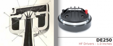
An OS waveguide does (and this is clear from the data on my website) yield a wider directivity than the attached driver's wall angles. That is clearly the case with the DE250 which has an exit angle of 6 degrees and yet has a HF coverage of 45 degrees.
Doesn't that DE250 have something like a 1/2" exit size? I fail to see how you can discount the exit diameter of the device. You are saying the exit size is insignificant but then say a 4" exit driver would drop like a rock at higher frequencies? We are all having some disconnect in how we are communicating here is seems.
Earl,An OS waveguide does (and this is clear from the data on my website) yield a wider directivity than the attached driver's wall angles. That is clearly the case with the DE250 which has an exit angle of 6 degrees and yet has a HF coverage of 45 degrees.
The DE250 has a 1" throat exit of 6 degrees, but the throat is clearly too short to be a waveguide at VHF.
The JBL 24XX drivers have a 7.5 degree throat of sufficient length to be a narrow waveguide at frequencies above 10 kHz, if you placed an OS waveguide on those drivers, the VHF dispersion will still determined by the initial conical horn section wall angles.
Art
Attachments
Bigger exit means lower frequency of mass roll off. Beaming is a different issue.
That's exactly correct.
Earl,
The DE250 has a 1" throat exit of 6 degrees, but the throat is clearly too short to be a waveguide at VHF.
The JBL 24XX drivers have a 7.5 degree throat of sufficient length to be a narrow waveguide at frequencies above 10 kHz, if you placed an OS waveguide on those drivers, the VHF dispersion will still determined by the initial conical horn section wall angles.
Art
Too much hand waving for my taste.
Hi Earl:
I think you're getting what I'm saying about beaming, no misunderstanding. I have a tough time picturing a device without a diffraction slot expanding the dispersion at HF from the presumably beaming HF from the driver exit (though a simple short horn beaming is an oversimplification). The upside I mention is simply somewhat longer effective pathlength- just like mouth flare/termination, every little bit helps.
I think you're getting what I'm saying about beaming, no misunderstanding. I have a tough time picturing a device without a diffraction slot expanding the dispersion at HF from the presumably beaming HF from the driver exit (though a simple short horn beaming is an oversimplification). The upside I mention is simply somewhat longer effective pathlength- just like mouth flare/termination, every little bit helps.
I can see where Earl is coming from. We (maybe I should say I) assume that the diameter is setting the directivity. On a wg the mouth dia sets the lower control limit, and for a piston on a baffle the dia determines where the pattern is narrowing and we use that as roughly the -6 db region. At 1" we have a wl of 13.5khz, and yet my waveguides based on os geometry maintain a 90° pattern up to a little over 16khz. It looks to me like diaphragm breakup in my case is what's causing the deviation in the pattern up top. I take Earl's word for it that the os is the lowest diffraction contour, but is it precisely that (diffraction) that causes the os to maintain the pattern above 1wl of the CD exit dia?
Hi Earl:
I have a tough time picturing a device without a diffraction slot expanding the dispersion at HF from the presumably beaming HF from the driver exit.
I agree that it is non-intuitive. That doesn't make it wrong.
Well done Nate - you are listening. You have it right. Not intuitive, but correct.I can see where Earl is coming from. We (maybe I should say I) assume that the diameter is setting the directivity. On a wg the mouth dia sets the lower control limit, and for a piston on a baffle the dia determines where the pattern is narrowing and we use that as roughly the -6 db region. At 1" we have a wl of 13.5khz, and yet my waveguides based on os geometry maintain a 90° pattern up to a little over 16khz. It looks to me like diaphragm breakup in my case is what's causing the deviation in the pattern up top. I take Earl's word for it that the os is the lowest diffraction contour, but is it precisely that (diffraction) that causes the os to maintain the pattern above 1wl of the CD exit dia?
The cause? The fact that the contour is precisely what the wave front can follow. No other contour does that.
the phase plug is supposed to shape the wavefront - it presumably should be a spherical front, normal to the driver throat exit angle - not a flat piston plane wave
That's not true. Read Bob Smith's paper. His intent was a flat wave front not a spherical one (except that it does not actually do that.) There are no other publications about phase plugs that I know of, except my patents, and they completely contradict the Bob Smith paper.
Bigger exit means lower frequency of mass roll off. Beaming is a different issue.
That's exactly correct.
To be exact, isn't it the (possibly) higher Mms compared to motor force, not the size of the exit?
")
There are 2" exit drivers with different sizes of radiating surfaces, some have 3" VC, some have 4", some are ring radiators etc. That's why above statement is misleading, but of course I understand the meaning behind it (bigged domes usually don't go as high).
Besides Mms, mass rolloff point/mass break point also depends on the motor force which drives the radiating surface, the relation between the mass and the force. Mass break point formula is on page 6: https://www.jblpro.com/pub/technote/tn_v1n08.pdf
Earl,
The DE250 has a 1" throat exit of 6 degrees, but the throat is clearly too short to be a waveguide at VHF.
The JBL 24XX drivers have a 7.5 degree throat of sufficient length to be a narrow waveguide at frequencies above 10 kHz, if you placed an OS waveguide on those drivers, the VHF dispersion will still determined by the initial conical horn section wall angles.
Art
Too much hand waving for my taste.
I would also bet my money like Art.
With the built-in horn, the contour of the wavequide as whole including the path inside the driver, is not (as) pure OS anymore, thus higher frequencies are directed.
Same thing what we have said, just presented in a different angle.
Last edited:
- Home
- Loudspeakers
- Multi-Way
- Geddes on Waveguides