Hello Michael,
IMHO the GD due to the crossover itself has not to be considered in that discussion because we yet see that we have solutions for the results of the summation of a low-pass and a high-pass crossover to have a (quasi) constant delay.
Then you try to compare GD in horns and in conventional loudspeakers. For conventional loudspeakers the load itself is at the origin of the GD non linearity. The closed enclosure operates as having a second order transfer function and a bass-reflex operates as having a 4th order tranfer function, with the corresponding phase non linearity). So there is theorically no main difference between horns and other loads. But in practice a high order load (as a BR) is rarely used to load a loudspeaker in the medium.
Best regards from Paris, France
Jean-Michel Le Cléac'h
What I want to clarify is something different - *if* on the example given you put a XO on top where the GD still looks good for now, *then* GD is back again at XO point - for any solution that can be realized passively at least...
Hence I said, I do not see how you ever will be able to "lower" GD (or increase useful BW) and also its no explanation that direct radiators seem to have quite different sonics in this department under comparable conditions regarding FR phase GD CSD etc....
Michael
Did you guys ever look at the topic of this thread? Could you take all this rambling somewhere else?
A remarkable statement, Earl !
Are you in fear of just another "Waterloo" or are you t(s)elling us that horn honk - per se - does not apply to oblade spheroide horn contour ?
In the end - you know - there will be comparison of contours again – but I don't think we *have to* discuss the matter exactly here – so I start another thread:
http://www.diyaudio.com/forums/multi-way/161627-horn-honk-wanted.html#post2090939
Either way – regarding the formal frame of the issue under discussion, I'd like it to be it rather called a *thesis* about horn honk....
You are welcome to contribute at any time !
Michael
Last edited:
As far as your contribution.. well that's up to you.
You are welcome to contribute at any time !
Michael
I am careful about the posts that I respond to - there are a lot of jerks out there.
I am careful about the posts that I respond to - there are a lot of jerks out there.
It's never been about the poster, it's about the post.
If the post (or posts) have a fundamental problem (abusive or repeatedly off-topic) - then sure, take care in responding (or simply stop responding) to that particular grouping of posts.
As far as Michael, Jean-Michel, Dennis, songsc, or jzagaja - none of their recent posts appear to either be abusive OR off-topic. Michael's latest post? ..yeah, but it was a response to your post that was also abusive (..i.e. "rambling"). (..in that you can't expect to "give" and not "get back" in return.)
Again, what's the problem with discussing the effects/solutions of phase rotation at the waveguide's exit? -Frankly I would think that this particular topic would "play in" well with your preferred design.
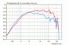
What's going on? Why BEM is not showing it?
What exactly BEM did not show you?
Michael
If the post (or posts) have a fundamental problem (abusive) - then sure, take care in responding
Did you guys ever look at the topic of this thread?
Geddes on Waveguides ? !!
Does this mean nobody else can answer questions? If this is so, why not just write up what one person wants to say and put it in a different section for reference? There were so many questions left unanswered that we would have to either let the thread die or continue discussion regardless.
What exactly BEM did not show you?
This resonance:
http://www.diyaudio.com/forums/multi-way/103872-geddes-waveguides-391.html#post2088817
JMLC stays flat, it's always reliable.
Example baffle:
Code:
Baffle
2.3000cm 	0.0000cm
2.5080cm 	1.5000cm
2.5318cm 	0.1000cm
2.5710cm 	0.1000cm
2.6249cm 	0.1000cm
2.6926cm 	0.1000cm
2.7731cm 	0.1000cm
2.8653cm 	0.1000cm
2.9682cm 	0.1000cm
3.0806cm 	0.1000cm
3.2016cm 	0.1000cm
3.3302cm 	0.1000cm
3.4655cm 	0.1000cm
3.6069cm 	0.1000cm
3.7537cm 	0.1000cm
3.9051cm 	0.1000cm
4.1400cm 	0.1500cm
4.4654cm 	0.2000cm
4.8877cm 	0.2500cm
5.5009cm 	0.3500cm
6.5924cm 	0.6000cm
9.1482cm 	1.3500cm
31.1010cm 	11.0997cm
31.8041cm 	0.3472cm
32.0092cm 	0.0970cm
32.2181cm 	0.0950cm
32.4307cm 	0.0929cm
32.6471cm 	0.0907cm
32.8670cm 	0.0885cm
33.0904cm 	0.0863cm
33.3173cm 	0.0841cm
33.5474cm 	0.0818cm
33.7808cm 	0.0795cm
34.0173cm 	0.0771cm
34.2568cm 	0.0747cm
34.4993cm 	0.0723cm
34.8683cm 	0.1039cm
35.2434cm 	0.0983cm
35.6243cm 	0.0926cm
36.0105cm 	0.0869cm
36.4017cm 	0.0811cm
36.7976cm 	0.0752cm
37.3322cm 	0.0909cm
37.8737cm 	0.0802cm
38.5588cm 	0.0849cm
39.3908cm 	0.0791cm
40.6529cm 	0.0715cm
41.6404cm 0.0162cmIf you would like to compare oblade sheroide horn contour with LeCleach horn contour here, you would have to show us measurement *and* simulation setup for *both*.
I'm pretty sure there is a simple explanation in that simulation setup does not reflect measurement setup in favor or disfavor for one or the other contour.
In addition :
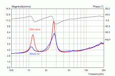
how does this bump in 12" OSWG + STX D800-Ti + 4.7uF look like in polar and impedance measurement ?
Michael
I'm pretty sure there is a simple explanation in that simulation setup does not reflect measurement setup in favor or disfavor for one or the other contour.
In addition :
how does this bump in 12" OSWG + STX D800-Ti + 4.7uF look like in polar and impedance measurement ?
Michael
Last edited:
how does this bump in 12" OSWG + STX D800-Ti + 4.7uF look like in polar and impedance measurement ?
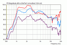
Like this (0/30/60 deg)
Attachments
I suspect 4.7uF electrolytic capacitor resonate with driver impedance? Real+HP means I convoluted measurement with 1st order lowpass to simulate ideal 4.7uF cap. Anyway JMLC offers best midrange and you can't change that 
Note: measurements taken with Bruel Kjaer 4149+2614 on 2610 measuring amplifier at distance 1 meter.
Note: measurements taken with Bruel Kjaer 4149+2614 on 2610 measuring amplifier at distance 1 meter.
Attachments
Last edited:
Given you seem to make this horns for Earls benefit – actually *he* should do the debugging – no?

Anyway - comparing impedance and SPL measurements you have shown, it seems, there is "real" problem involved with the contour you make – not just a fault in simu setup or the like
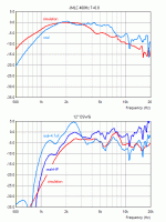
Here is what I got from a quick sim of the contour you posted – no 4.7uF EQing tho !
Without any baffle :


In infinite baffle :


Motor parameters and details of driver-horn-joint may not exactly fit your setup but what I see in this simus is more or less what you measure – the hump at ~2kHz clearly shows up.
Don't know why you couldn't catch it with AxiDriver ?
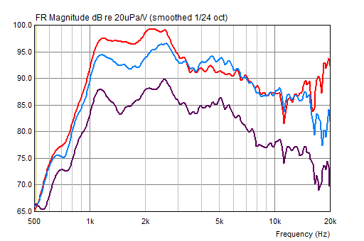
As for interpretation – IMO this specific mid band defect is *not* inherent to the oblade sheroide horn contour.
You can and should check out yourself what the impacts of a kink between origin (driver) and contour actually are.
http://www.diyaudio.com/forums/multi-way/103872-geddes-waveguides-78.html#post2082059
http://www.diyaudio.com/forums/multi-way/103872-geddes-waveguides-72.html#post1991238
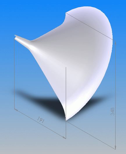
http://www.diyaudio.com/forums/multi-way/103872-geddes-waveguides-73.html#post2005959
Bottom line – you should not accuse Earls contour until you haven't double checked
The differences between my Gaussian MinPhase contour the LeCleach contour and oblade spheroide contour are quite distinct with respect to tolerating a "conical duct" in front of the horn contour....

Michael
Anyway - comparing impedance and SPL measurements you have shown, it seems, there is "real" problem involved with the contour you make – not just a fault in simu setup or the like
Here is what I got from a quick sim of the contour you posted – no 4.7uF EQing tho !
Without any baffle :


In infinite baffle :


Motor parameters and details of driver-horn-joint may not exactly fit your setup but what I see in this simus is more or less what you measure – the hump at ~2kHz clearly shows up.
Don't know why you couldn't catch it with AxiDriver ?

As for interpretation – IMO this specific mid band defect is *not* inherent to the oblade sheroide horn contour.
You can and should check out yourself what the impacts of a kink between origin (driver) and contour actually are.
http://www.diyaudio.com/forums/multi-way/103872-geddes-waveguides-78.html#post2082059
http://www.diyaudio.com/forums/multi-way/103872-geddes-waveguides-72.html#post1991238

http://www.diyaudio.com/forums/multi-way/103872-geddes-waveguides-73.html#post2005959
Bottom line – you should not accuse Earls contour until you haven't double checked
The differences between my Gaussian MinPhase contour the LeCleach contour and oblade spheroide contour are quite distinct with respect to tolerating a "conical duct" in front of the horn contour....
Michael
Last edited:
I disagree Michael. The "kink" is cut and almost does not exist. Much longer kink is in compression drivers we use. Another thing is simu difference, what kind of motor parameters and solver you use, is it a secret? I use Horn-Flat Diaph.axi example and change only the baffle and diaphragm diameter.
Please apply HP or export Level dB in Axi and paste here.
One can check DE250 impedance with 4.7uF cap in LSPCAD to see those peaks. It is driver horn/dependent - seldom observed with Tractrix+dome tweeter.
Please apply HP or export Level dB in Axi and paste here.
One can check DE250 impedance with 4.7uF cap in LSPCAD to see those peaks. It is driver horn/dependent - seldom observed with Tractrix+dome tweeter.
The "kink" is cut and almost does not exist.
*Almost* might be what you have to check out - at least if the contour data you gave is correct.
As said in one of the links provided - the OS is basically a diffraction horn - not that different from a axis-symmetric manta ray - just that the kink in the contour is shifted towards the throat.
This makes all the difference with respect to FR smoothness and other aspects IMO - but it also requires a driver that fits - not sure the screw on versions with their pretty long flare are the best choice here...
As for the LeCleach - this contour is the least affected by such drivers as it starts out with a very slow increase in angle - my contour is more sensible here and Earls is the most critical horn contour in this respect
Well just my 2ct ...
Michael
Last edited:
This implies Earl must use a lot of corrections in crossover also because of crossing at woofer breakup. That's why I use 2" aluminum coil. But I still see above resonance as mostly electrical not acoustical.
Minphase horn is far from being CD (especially in relation to size)- that's another story we need to solve.
Minphase horn is far from being CD (especially in relation to size)- that's another story we need to solve.
Another thing is simu difference, what kind of motor parameters and solver you use, is it a secret?
I adjusted for best fit with measurements as the data provided here:
D-800-Ti - STX Polski producent - kino domowe g?o?niki akcesoria
did not give any good match
Your 4.7uF cap EQing is degrading FR tracking between measurements and sim some further in this case - as the corresponding peaks in electric impedance get "inverse amplified"
Michael
Minphase horn is far from being CD (especially in relation to size)- that's another story we need to solve.
Size simply is a matter of low horn mouth reflection - once the directivity and bandwidth is set. You can cut down any horn in length but on one hand its no longer intact regarding diffraction alignment into free space and on the other hand the penalty is what you are just facing with the *kink* - just in another frequency department...
Besides that - in the range I claimed, my Gaussian MinPhase actually *is* CD - you and anybody else have seen its behavior beforehand - no need to complain about.
Keep in mind, the Gaussian MinPhase horn I developed *towards* CD - but even higher in my list was to keep inherent smooth sound field of LeCleach contour intact.
Though I think it came out very well in what I was after - I'm not saying there is no room for improvement - just make some thoughtful suggestions (possibly in the right thread) - I'm all ears !
Michael
- Home
- Loudspeakers
- Multi-Way
- Geddes on Waveguides
