The parts list and suggested Mouser part numbers can be found in the attached pdf file.
On the version "B" ..does this mean that we have the option of bypassing the power supply stage completely and just powering the boards from, say, an SMPS?
I have a TON of laptop type power bricks ranging in voltages, it might be ideal for me to do this. If I complete the version B boards, I should be able to drive them both using the 16vdc power brick I'm using for the MiniDSPs already?
I would not recommend a laptop SMPS! They sometimes have large amounts of ripple at the switching frequency and can produce a lot of emf. The reason you can power your other equipment with these kind of supplies it is that the equipment has its own onboard dc regulator. Anyway you need a dual polarity supply.
The "B" version is more or less intended for use with an "A" version should you need more than 4 channels. The low noise regulated power supply from the "A" version is powering both boards. You could use a separate dual rail power supply, e.g. +/-15V, but it should probably be a low noise linear type.
I'll probably end up just getting the mcm ones for now. I might call Antec and see when they plan on having more of the torroids.
Sorry if I'm a bit frustrating on this power supply business, I've just got a bunch of spare stuff sitting around that I'm always looking to re-purpose.
Sorry if I'm a bit frustrating on this power supply business, I've just got a bunch of spare stuff sitting around that I'm always looking to re-purpose.
I managed to find a pair of 12.6v@ 300mA trafos. They seem to behave just as the mcm ones did for you, giving roughly 16v unloaded. I found a couple of larger 16v (labelled) ones as well, but their unloaded voltage was pushing the 21v mark.
Those should be fine, although you might want to check the regulated voltage and the voltage of the AC secondary if you will power additional boards from the PS on the first one. The regulators need about 3V difference between input and output and there is a small voltage drop in the CRC smoothing caps. You will probably be fine but it's a good idea to double check the voltages just to know that you are in the clear (or not).
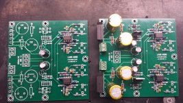
Yay, boards arrived! I had to make a couple of substitutions on the BOM for some of the caps, Mouser is backordered on the 1800uF and 22uF. I subbed them for higher voltage ones. No biggie, they're only a couple of cents more expensive.
EKMG101ELL220MHB5D United Chemi-Con | Mouser
UHE1H182MHD6 Nichicon | Mouser
EKMG101ELL220MHB5D United Chemi-Con | Mouser
UHE1H182MHD6 Nichicon | Mouser
Edit: The smoothing caps can be higher than 1800uF, can't they? I have some 63v 2200uF laying around.
That's right, as long as they are 7.5mm lead spacing you are fine. Usually these will be either 16mm or 18mm diameter. Both sizes will work.
One final question if I may before the parts arrive and I start building. Do you think it's better to build both boards complete with power supply and drive them both with the two transformers, or do you think I should build only one board with the power supply components and power the second one from the DC +/- from the first?
Edit: I've already ordered parts for both boards complete, so there wouldn't be any cost savings omitting the power supply from one of them.
Edit: I've already ordered parts for both boards complete, so there wouldn't be any cost savings omitting the power supply from one of them.
One final question if I may before the parts arrive and I start building. Do you think it's better to build both boards complete with power supply and drive them both with the two transformers, or do you think I should build only one board with the power supply components and power the second one from the DC +/- from the first?
Edit: I've already ordered parts for both boards complete, so there wouldn't be any cost savings omitting the power supply from one of them.
I don't think that you should connect each transformer to more than one board. I would leave off all the PS components and the except the 220uF caps (C33 & C43) and power that board from the other that has the full PS. That would work if the two boards can be next to each other. Alternately you can use additional transformer(s) to power the second board so that they are fully independent.
Getting ready for power up and testing. Just wanted to make sure you didn't spot any glaring errors before I do so...specifically, the orientation of the OP amps, I have them with the dot next to R13/R15. Is that right?
I'm probably way more excited than I should be about these things, it's my first real attempt at building something like this
Edit: Oh, forgot to mention, there's a minor error on the BOM, R13 - R16 (68R) are listed as caps (C13-C16).
Edit2: Doh, I just noticed the silkscreen dot on the boards for OP Amp orientation, duuuuuur. ¬.¬
Attachments
Last edited:
Getting ready for power up and testing. Just wanted to make sure you didn't spot any glaring errors before I do so...specifically, the orientation of the OP amps, I have them with the dot next to R13/R15. Is that right?
I'm probably way more excited than I should be about these things, it's my first real attempt at building something like this
Edit: Oh, forgot to mention, there's a minor error on the BOM, R13 - R16 (68R) are listed as caps (C13-C16).
Edit2: Doh, I just noticed the silkscreen dot on the boards for OP Amp orientation, duuuuuur. ¬.¬
The build looks fine to me. Thanks for catching the error on the BOM. You are correct, those are the 68R resistors R13-R16. I must have typed the wrong letter. I will update my BOM list.
The build looks fine to me. Thanks for catching the error on the BOM. You are correct, those are the 68R resistors R13-R16. I must have typed the wrong letter. I will update my BOM list.
Oh, I think I found an oops, I might have C24 reversed. While I was on autopilot, I mounted it opposite after placing it's brother, but I just noticed you had marked a + with black marker and they should both be placed positive to the left (or up in my picture).
Oh, I think I found an oops, I might have C24 reversed. While I was on autopilot, I mounted it opposite after placing it's brother, but I just noticed you had marked a + with black marker and they should both be placed positive to the left (or up in my picture).
Follow the mark I made for polarity for C24. I corrected an error on the silkscreen using a sharpie to show the correct orientation. You can see it marked on the left board in the image below:
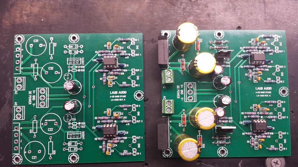
If you powered it up already, don't worry the cap it still OK but you might destroy it taking it out.
Always, always, always double check the polarity when inserting a polarized (e.g. electrolytic) cap.
I haven't powered it up yet. I'll flip that cap around before I do. Luckily, I ordered two complete boms, so I've got two more of those caps should one of the leads pull out.
I should have enough time to finish up the case and get a power up test today or tomorrow morning. Hopefully no smoke!
I should have enough time to finish up the case and get a power up test today or tomorrow morning. Hopefully no smoke!
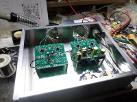
First power on test, no smoke! I think I might need larger trafos after all, I get +15.06v, -14.89v with just the gain boards (both powered up), plugging in the MiniDSPs drops the positive to +13.89v
Do you think that's ok, or is that a sign that I'm trying to squeeze too much out of these little trafos?
Edit: Oh, I forgot to mention..yes, I did destroy that cap getting it out. Part of the issue is the legs on those caps just baaaaarely fit through the eyelets on the board. It looks as though they're a bit bigger than the silkscreen on the board suggests it's expecting, so even after being vacuum desoldered, it still took pliers to liberate the legs from the board. Even the first time, they took lots of wiggle wiggle wiggle to get them seated down into their spot.
Oh, and that board was missing the correction, so I feel a little better, haha!
Attachments
Last edited:
First power on test, no smoke! I think I might need larger trafos after all, I get +15.06v, -14.89v with just the gain boards (both powered up), plugging in the MiniDSPs drops the positive to +13.89v
Do you think that's ok, or is that a sign that I'm trying to squeeze too much out of these little trafos?
Edit: Oh, I forgot to mention..yes, I did destroy that cap getting it out. Part of the issue is the legs on those caps just baaaaarely fit through the eyelets on the board. It looks as though they're a bit bigger than the silkscreen on the board suggests it's expecting, so even after being vacuum desoldered, it still took pliers to liberate the legs from the board. Even the first time, they took lots of wiggle wiggle wiggle to get them seated down into their spot.
Oh, and that board was missing the correction, so I feel a little better, haha!
Nice little build coming along there. Here are a couple of thoughts:
The two small transformers are fine for powering the op-amps on the gain stage boards. These don't require much current. On the other hand, the miniDSP does need a hundred milliamps of current or so, and as you discovered when you connect it to the PS the voltage falls. In fact, the positive rail is no longer being regulated when it dips below the 15v nominal level that the regulators are set to and this may induce some noise.
I don't think that you mentioned you would be powering your miniDSP from the PS before. Connecting the digital load may induce some noise into the gain circuit linear supply. Usually you would decouple the supply to the digital circuit to reduce this effect - you would need to insert the L and C components manually. See for info: Decoupling
This still would not solve the problem of the sagging positive rail, however, and a good solution would be to use a separate PS for the miniDSP and connect the grounds. It will be less expensive compared to buying two more transformers. You could fit a small wall wart type of supply next to the two transformers for instance. These are lots of options for around $10 plus or minus. For example, you can find lots of small switching wall warts like this one for $8:
DC Converter 9V 1 5A 3 8mm Plug Thin Pin Switch Power Supply Adapter 100 240AC | eBay
Since some cheap switching supplies radiate a lot of EMF, a linear supply might be a better option, like these:
GPU410900500WDOO: JAMECO RELIAPRO: Power Supplies & Wall Adapters
9 VDC 600MA REGULATED POWER SUPPLY | All Electronics Corp.
I would stick with 9Vdc supplies or maybe 12Vdc. The miniDSP has on-board 3.3v regulators and the higher the input voltage the more heat they will dissipate. You may already have a regulated wall wart supply in your parts bin but you never know how much radiated noise these generate so try it and see before buying anything.
Sorry that I sent you one board without the C24 polarity correction. I tried to carefully mark each one but obviously I missed it. Also, some manufacturers use slightly different lead diameters and when I was doing the layout I probably happened to pick one with slightly thinner leads. I will open up the hole diameter on the next go-around. Thanks for mentioning it.
Good idea..there's plenty of room in there for another supply, so I'll probably do that. I could always just stick the one I was using in there.
Besides the now additional transformer, I'm almost ready to hook this up to an amplifier and a cheap speaker to make sure it's making music before I try it in my system.
On the 15v regulators, should I be concerned that my negative rail is -14.89v ?
Besides the now additional transformer, I'm almost ready to hook this up to an amplifier and a cheap speaker to make sure it's making music before I try it in my system.
On the 15v regulators, should I be concerned that my negative rail is -14.89v ?
On the 15v regulators, should I be concerned that my negative rail is -14.89v ?
No, this is just within the voltage regulation spec for the 337 when you take into account the resistor tolerances. I see this all the time.
- Status
- This old topic is closed. If you want to reopen this topic, contact a moderator using the "Report Post" button.