hi all,
well i'm a begginer in electronics, so i'd like to know some stuff that must be basic, but it's been bugging me a lot last days
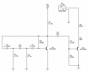
there's this Vibrato Circuit i found:
i had some doubts, but i assembled it anyways
...
it didn't work, not even a slight scratch or noise, or humming, nothing, its dead
now, this was my "doubt" before trying to build it:
is that OUT line correctly placed along the IN line???
i mean... for an audio circuit, where a signal is supposedly filtered and messed up and stuff... can the output signal be contiguous -in the circuit- to the In line??
in the website ( http://www.lh-electric.4t.com/projects/t_circ.htm )the author states that any general purpose PNP or NPN transistor should work
i used two 2N3904
are the transistors the problem?
is this circuit?
what is it??
thanks
well i'm a begginer in electronics, so i'd like to know some stuff that must be basic, but it's been bugging me a lot last days
there's this Vibrato Circuit i found:
An externally hosted image should be here but it was not working when we last tested it.
i had some doubts, but i assembled it anyways
...
it didn't work, not even a slight scratch or noise, or humming, nothing, its dead
now, this was my "doubt" before trying to build it:
is that OUT line correctly placed along the IN line???
i mean... for an audio circuit, where a signal is supposedly filtered and messed up and stuff... can the output signal be contiguous -in the circuit- to the In line??
in the website ( http://www.lh-electric.4t.com/projects/t_circ.htm )the author states that any general purpose PNP or NPN transistor should work
i used two 2N3904
are the transistors the problem?
is this circuit?
what is it??
thanks
Then second transistor is drawn upside down - the emitter should be connected to ground.
Circuit is actually tremolo, not vibrato. It should modulate the volume level of the signal going through it.
The connections are correct. The first transistor forms a low frequency oscillator with P1 being the "rate" control. This is fed to P2 ("depth" control). The second transistor in conjunction with the 100k and 39k forms a variable voltage divider.
Cheers
I simulated it in spice and should work.. The first transistor is indeed the oscilator and it should not be loaded too much, so a 100K resistor in series with its output before the 47nF cap should ensure that....
The seconmd transistor is not drawn wrong.. it actually doesn't matter how it is connectec......it works both ways..
If the circuit doesn't work.. try to find out which parts doesn't work..disconnect the two transistors at the 500K pot... check if the first transistor is indeed oscilatting at around 8Hz (P1 in the middle) ... and check if sound if coming through if you connect input and output... then come back here again...
goodluck,
Thijs
whoa
can't believe it..
i've been asking people out w/ this all last week and no one replies or advices something clear enough to try it
then i come here and voilá... lots of replies, and lots of things to try and do
thank you guys for being kind, helpful and nice
should be back soon with what i got
see you,
and thanks!
by the way ( before attempting any changes)...
now that i think about it, capacitors have voltage settings. i didn't mind this, but now... seeing a simulation worked and my circuit didn't, i'll list caps used and their specs, to know if they are the problem
C1: 47n - 473J, 100v
C2: 4.7u polar - 50v
C3: 1uF - 160v
C4: 0.68uF - (this one is special... the guy at the store didn't have .68, so he gave me 2 caps that put in paralell give .69) 2A224K and 474J
..about doing this schematic and not some other smoother effects.. ..i did choose this one because it seemed very simple ( and inexpensive.... well, and because i found all parts in the same store..... which is the best i can get here in Antofagasta)
The capacitors voltage values are just fine.. go ahead and build it.. I'm gonna build one too tommorow, just for fun.. I play a little guitar and build several distortion effects allready, yet I would like a tremelo effect.. so why not.. I just decided to try your circuit....It really should work,
Thijs
Thijs
yeah, i'll rebuild it from scratch... i must have fried a transistor or something in the process
i'm doing it for my CT-350 ( casio keyboard)... the jazz organ preset just cries for tremolo... despite the noises it'll probably do while i'm not doing anything w/ the keyb', that'll sure add some "vintage" cheesyness to the already cheesee casio
i'm doing it for my CT-350 ( casio keyboard)... the jazz organ preset just cries for tremolo... despite the noises it'll probably do while i'm not doing anything w/ the keyb', that'll sure add some "vintage" cheesyness to the already cheesee casio
Hi again,
So I build it.. slightly modified to run of a 9volt battery and PNP transistors only.. I didn't had any NPN anymore.... on my osciloscope it looks pretty good, but the sound is a bit too drastic ON/OFF ... not very liquid... and I had to use a Proco RAT distorion pedqal as a buffer.. using it dry resulted in a muffled sound with little treble... but it does work.. instantly.. ... and it does a good job for just a handful (actually less) on parts that can be found on my floor...
goodluck,
Thijs
Attachments
no luck here...
installed it in a protoboard ( so i can change components whenever i detect an error), used fresh components, checked every res, cap, everything.... and nothing
i'm feeding it w/ 12Volts... would that be the problem?
thats the max voltage i can feed it with, however..... is there a simple mod that could allow me feed it w/9V?? ( and still be using the 3904's)
thanks
also..
a pair of questions about your schematic:
-are the transistors critical for th eeffect? or can i use any general purpose PNP?? ( i've read somewhere that i can place a NPN instead of a PNP if i switch all polarities... that means i could use the 3904's right?)
-why the 4.7uF capacitor appears as non-polar?? is it that way?
-where are both pots??
-now about the original effect ( and yours)... why is there a 100k resistor at the very beggining? ..i know you said it is there to create a voltage divider.. now, am i suppossed to hear the original audio signal when the circuit is not voltage feeded?
thanks again
cya!!
about the caps...
what are their specific polarities? (if there are any)
..by the way.. i assembled your version of the circuit.. and the only thing i get is a pulsating noise through the audio signal ( this when i switch the 100k res for a 220ohm res) ...damn, i want it to work...
what are their specific polarities? (if there are any)
..by the way.. i assembled your version of the circuit.. and the only thing i get is a pulsating noise through the audio signal ( this when i switch the 100k res for a 220ohm res) ...damn, i want it to work...
i'm feeding it w/ 12Volts... would that be the problem? thats the max voltage i can feed it with, however..... is there a simple mod that could allow me feed it w/9V?? ( and still be using the 3904's)
12V or 9V shouldn't matter.. 2n3904 should work at both values... I use 9V so I can use a single battery.. easy and noiseless....
-are the transistors critical for th eeffect? or can i use any general purpose PNP?? ( i've read somewhere that i can place a NPN instead of a PNP if i switch all polarities... that means i could use the 3904's right?)
The transistors aren't critical... I use BC560b , Hfe was about 400.. you can use PNP or NPN, just reverse polarity... PNP uses a -9V supply, NPN uses a +9V supply... the second transistor can be either NPN or PNP.. doesn/t matter...
It's a polar electrolitic... -side goes to the other cap.. +side goes to the first...transistor..-why the 4.7uF capacitor appears as non-polar?? is it that way?
I didn't use pots.. just used resistors with proper values instead..-where are both pots??
-now about the original effect ( and yours)... why is there a 100k resistor at the very beggining? ..i know you said it is there to create a voltage divider.. now, am i suppossed to hear the original audio signal when the circuit is not voltage feeded?
The 100K resistor is there to weaken the signal. It is a essential part, do not remove it. When the second transistor is driven 'ON' by the oscilator (1st transistor) the second transistor has a very low resistance, even in absence of a voltage supply.. So the signal get's attenuated
39K / 100K+39K or 3.6 times.. about 11dB
When the second transistor is not driven but is 'OFF' , the signal get through the 100K, but doesn't get attenuated through the 39K... so it cycles through attenated/not attenuated.. just the effect we are looking for..
When the whole circuit is left without a voltage suypply, you should here the original signal, since the second transistor cann't be driven 'ON'.. it might be a weaker signal because of the 100K that's allways there.. that's why I used a high impedance buffer...
..by the way.. i assembled your version of the circuit.. and the only thing i get is a pulsating noise through the audio signal ( this when i switch the 100k res for a 220ohm res) ...damn, i want it to work...
A pulsating noise is good that means the oscilator is working.. it is pulsating at a proper frequency (about 8Hz)? The 100K is essential.. do not modify it..
goodluck..
what are their specific polarities? (if there are any)
I just realised... in my version (using PNPs and a -9V supply) the only polar cap is the 4.7uF.. the -side should go to the transistor, the +side to the other cap...
In the original version (using NPNs and a +9V supply) this cap should be flipped around...
it's alive!!!
man, first of all, i want to THANK you for being so patient to explain me every detail of this thing..... for giving me strength, and even for having make an alternate version of it
well, bet you couldn't guess were was located the problem...
it was external
it was the defficient audio probe i set up for testing purposes.... the out impedance was insufficient, so i could not hear anything, even when the circuit was running perfectly
fixed that and NOW i can hear the audio tremulating and stuff
after some tweaks ( like reversing that polar cap, or altering the value of the 39k filter stage), the tremolo can variate from a very subtle oscillation to a very deep alteration of the original source, to a chopper-like effect, which is cool as hell!!
thanks a lot, i really appreciate your kind efforts
i've learnt a lot and now i want to do more effects
thanks for everything, cya!!
no problem, I'm glad I could help.. You're right about the modulation depth: best to controll it by using a 47K ..100K? potmeter instead of the 39K resistor... Mine works pretty good also.. allthough it picks up a lot of hum... have fun.. come back with some other guitarFX if you want...Cheers,
Thijs
- Status
- This old topic is closed. If you want to reopen this topic, contact a moderator using the "Report Post" button.
- Home
- Live Sound
- Instruments and Amps
- help with this Vibrato Circuit