HI this is my first post as a newb here so hoping Ive landed this in the right place
From time to time I've DIY racked and fixed old pre amps, tube pre amps etc but only at a pretty basic level (eg cap replacement, basic signal tracing etc) and not where I would be taking any chances with the circuit beyond what I know. Also very aware of the dangers with high voltage here.
Been reading up on tube operaton and my physics is not great but understand the basic concepts to a point…
I’m just troubleshooting what I initially thought was a bad connection in my single valve (6gw8) Goldentone guitar amp ( Aussie practice amp from the 60’s). Attached is a link to a schematic (with thanks to J Mumford and C Lilly) that is pretty much identical to my amp except for one or two resistor values.
https://www.ozvalveamps.org/electravox/60s electravox single valve amp-p-jm.jpg
I think a good chance I’m dealing with a bad tube but I have swapped out another tube and both show identical symptoms. Before I go searching for another 6gw8 I was wondering if it could be a different problem eg.bias /voltage/ ac ripple?
Symptoms as follows….
Initially signal faded and disappeared after a certain amount of playing but was an intermittent thing..
Was able to bring it back temporarily and intermittently by addressing contact/ solder at tube pins but now the output is consistently weak have tensioned socket etc to no avail.
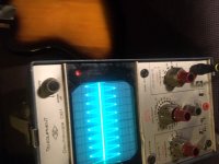
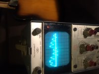
The triode stage appears to be amplifying as it should and a good signal goes in to the grid post volume and tone pot at the pentode stage but comes out weak and distorted at the anode (which makes me think either something wrong internally with the tube or some issue with voltage /current/ bias?)
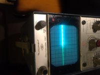
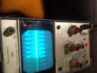
Attached are some photos on my old oscilloscope showing a 440hz sine wave coming in and at the final stage before it hits the output transformer.
I took some voltage measurements at key points in reference to the schematic as well….
Voltage at triode plate (C) is 147vdc (schematic indicates 82vdc ) stock resistor from point B to C on my amp is 100k (not the recommended 220k)
Screen Voltage at Point (B ) is 260vdc (recommended is 250vdc)
Plate voltage at pentode (A) is 320vdc (as opposed to recommended 309vdc )
Heater voltage is 7.02 v ac (measured from pin 4 to 5) recommended is 6.2 vac
Btw I did see some ac on the (A) voltage but not a huge amount
Original caps replaced a few years ago
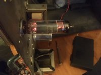
Scope pics attached and finally a picture of the tube glow if that helps : )
Just thought this might be a classic indication of either bad tube or another common symptom ? Not sure… if anyone has the time to share expertise on this that’d be really appreciated!
Thanks
Tim
From time to time I've DIY racked and fixed old pre amps, tube pre amps etc but only at a pretty basic level (eg cap replacement, basic signal tracing etc) and not where I would be taking any chances with the circuit beyond what I know. Also very aware of the dangers with high voltage here.
Been reading up on tube operaton and my physics is not great but understand the basic concepts to a point…
I’m just troubleshooting what I initially thought was a bad connection in my single valve (6gw8) Goldentone guitar amp ( Aussie practice amp from the 60’s). Attached is a link to a schematic (with thanks to J Mumford and C Lilly) that is pretty much identical to my amp except for one or two resistor values.
https://www.ozvalveamps.org/electravox/60s electravox single valve amp-p-jm.jpg
I think a good chance I’m dealing with a bad tube but I have swapped out another tube and both show identical symptoms. Before I go searching for another 6gw8 I was wondering if it could be a different problem eg.bias /voltage/ ac ripple?
Symptoms as follows….
Initially signal faded and disappeared after a certain amount of playing but was an intermittent thing..
Was able to bring it back temporarily and intermittently by addressing contact/ solder at tube pins but now the output is consistently weak have tensioned socket etc to no avail.
The triode stage appears to be amplifying as it should and a good signal goes in to the grid post volume and tone pot at the pentode stage but comes out weak and distorted at the anode (which makes me think either something wrong internally with the tube or some issue with voltage /current/ bias?)
Attached are some photos on my old oscilloscope showing a 440hz sine wave coming in and at the final stage before it hits the output transformer.
I took some voltage measurements at key points in reference to the schematic as well….
Voltage at triode plate (C) is 147vdc (schematic indicates 82vdc ) stock resistor from point B to C on my amp is 100k (not the recommended 220k)
Screen Voltage at Point (B ) is 260vdc (recommended is 250vdc)
Plate voltage at pentode (A) is 320vdc (as opposed to recommended 309vdc )
Heater voltage is 7.02 v ac (measured from pin 4 to 5) recommended is 6.2 vac
Btw I did see some ac on the (A) voltage but not a huge amount
Original caps replaced a few years ago
Scope pics attached and finally a picture of the tube glow if that helps : )
Just thought this might be a classic indication of either bad tube or another common symptom ? Not sure… if anyone has the time to share expertise on this that’d be really appreciated!
Thanks
Tim
Attachments
Than the pentode section is passing 33 mA, which seems low to me (but because of the highish anode voltage, it's still very near the maximum anode dissipation of 9 Watt). The datasheet shows a total current (so Ia + Ig2) of about 45 mA at Vg2 = 245 V and Vg1 = - 6 V (the extra current would probably lower Va and Vg2 a bit).
Since you wrote that the signal at the grid of the pentode section is in order, I can't think of something better than to point at the power beam section of the 6GW8 as the culprit.
Since you wrote that the signal at the grid of the pentode section is in order, I can't think of something better than to point at the power beam section of the 6GW8 as the culprit.
Nifty! I've never seen a production single-valve guitar amp before. I'm assuming gain was fairly marginal when new? Clean tones only, no overdrive?...single valve (6gw8) Goldentone guitar amp...
Anyway - the thing that stands out to me like a searchlight beacon is the way the input stage (triode) is biased. That enormous 10 Meg grid resistor, and no cathode resistor at all - that is grid leak biasing. It is ancient, unreliable, trouble-prone, unstable as the valve ages, and, most likely, causing the problems you've been experiencing.
I would say your instincts were very good!
The fix is pretty easy. A few small changes will get rid of the troublesome grid-leak biasing, and replace it with self-biasing, which is the bee's knees for simple triode gain stages.
I've done the necessary math for you (pretty loadline and operating point picture attached), and all you have to do is make a couple of little changes:
1) Remove the 10 Meg resistor and replace it with a 1 Meg resistor.
2) Insert a 2k resistor (1/4W will do, or 1/2 W is fine too) between the triode cathode and ground, i.e., pin 2 and ground of the 6GW8.
3) Wire an electrolytic capacitor in the range of 4.7 uF - 10 uF across the 2k cathode resistor.
The capacitor is polarized, make sure the (+) side goes to the cathode, and the (-) side to ground.
This type of cap also has a maximum voltage rating. In the circuit shown, the cap will only have about 1.5 volts DC across it. You can use any 4.7uF - 10 uF cap that has a voltage rating of more than 3 volts. If you want a specific number, use a 25V cap.
That's it. Done. Your triode will now bias up stably. The anode should settle somewhere in the vicinity of 180 volts DC, but the exact value isn't too important as long as its reasonably close to 180 V.
I also edited the schematic you posted to reflect the changes I suggested, as well as the 100k triode anode resistor you have.
-Gnobuddy
Attachments
Thanks Gnobuddy! I was perplexed by that set up and then read about grid leak biasing which also seemed to be one way of saving on components that weren't cheap at the time. Doesn't seem to be standard for Goldentones either, they made some great larger amps really beautiful aesthetically too. By the time I've sourced a replacement valve I should prob do as you suggest for future stability thanks for the step by step that is extremely helpful! Ive enjoyed recording with this amp its very quiet (4 watts?) but has very nice mid range and overdrives when pushed really nicely but yes gently... I don't think Ive ever heard it get shreddy or brittle on that front.
You're very welcome. Glad to be able to help!
I was a member of Aussie Guitar Gearheads (AGGH) for a few years. I was particularly impressed by Roly Roper and Darryl Hoy, whose posts were always interesting and often informative. Eventually I accidentally got locked out (forgot my password), failed to get a response from a moderator after several weeks and many emails, and gave up.
In our present era with tons of available cheap stomp-boxes (effects pedals), it would be easy to add any bells and whistles you wanted.
I'd like to make a couple more comments on the schematic itself. Things you might want to consider changing, unless your goal is to keep the amp in original condition.
1) The network of 220k resistors at the input throws away half the available voltage gain, for no good reason that I can see. (Perhaps to keep the amp from overdriving, which might have been thought to be rude and unacceptable when it was new?)
At any rate, snipping out the 220k resistor across that 470 pF cap would give you another 6 dB of gain.
2) The remaining two 220k resistors could be replaced with 12k resistors, or just parallel one 12k with each of the existing 220k resistors, leaving the 220k resistors in situ. This will reduce hiss a bit, though hiss might not be an issue in such a low-gain amplifier.
3) If you convert the triode to self-bias as suggested in my previous post, you no longer need that 0.01uF/400V cap at the input (grid of V1a). It can be removed and replaced with a wire. (But it won't hurt anything to leave it in place.)
4) When changing to self-bias, the value of the cathode resistor sets the quiescent bias voltage, and changing the resistor will cause slight changes in timbre and available headroom.
The 2k cathode resistor value I suggested will centre-bias the triode and give you the most headroom. Most of Leo Fender's vintage amps used centre-biasing in the preamp valves.
But if you like to experiment, you can tinker with the value of that resistor. Anything between about 1k and 4k should still result in a usable amplifier, with accompanying changes in headroom and timbre. The 4.7uF - 10 uF cap can remain unchanged for these experiments.
-Gnobuddy
What a pity most of these uniquely Australian valve guitar amps are largely unknown to the rest of the world.Yellow Cab said:...Goldentones...made some great larger amps...
I was a member of Aussie Guitar Gearheads (AGGH) for a few years. I was particularly impressed by Roly Roper and Darryl Hoy, whose posts were always interesting and often informative. Eventually I accidentally got locked out (forgot my password), failed to get a response from a moderator after several weeks and many emails, and gave up.
I like low-power guitar amps too. I guess I have sensitive ears - one watt can be deafeningly loud to me.Yellow Cab said:...(4 watts?)...
There are no tone controls at all, so you're hearing more or less what comes out of the guitar pickup itself.Yellow Cab said:...very nice mid range...
In our present era with tons of available cheap stomp-boxes (effects pedals), it would be easy to add any bells and whistles you wanted.
I'd like to make a couple more comments on the schematic itself. Things you might want to consider changing, unless your goal is to keep the amp in original condition.
1) The network of 220k resistors at the input throws away half the available voltage gain, for no good reason that I can see. (Perhaps to keep the amp from overdriving, which might have been thought to be rude and unacceptable when it was new?)
At any rate, snipping out the 220k resistor across that 470 pF cap would give you another 6 dB of gain.
2) The remaining two 220k resistors could be replaced with 12k resistors, or just parallel one 12k with each of the existing 220k resistors, leaving the 220k resistors in situ. This will reduce hiss a bit, though hiss might not be an issue in such a low-gain amplifier.
3) If you convert the triode to self-bias as suggested in my previous post, you no longer need that 0.01uF/400V cap at the input (grid of V1a). It can be removed and replaced with a wire. (But it won't hurt anything to leave it in place.)
4) When changing to self-bias, the value of the cathode resistor sets the quiescent bias voltage, and changing the resistor will cause slight changes in timbre and available headroom.
The 2k cathode resistor value I suggested will centre-bias the triode and give you the most headroom. Most of Leo Fender's vintage amps used centre-biasing in the preamp valves.
But if you like to experiment, you can tinker with the value of that resistor. Anything between about 1k and 4k should still result in a usable amplifier, with accompanying changes in headroom and timbre. The 4.7uF - 10 uF cap can remain unchanged for these experiments.
-Gnobuddy
If the power supply specs on the schematic are correct, there may be the capacity to adds an additional preamp valve.
6gw8 draws 700ma heater current I believe.
The schematic states 2amps are available for the heaters.
Likewise the HT current available is stated as 60ma.
The 6gw8 is drawing 32ma as stated in the posts.
If there is an extra hole drilled in the chassis, perhaps one input could be made a high gain input.
Perhaps an ef86 either in parallel or cascaded with the 6gw8 triode.
There are many different vox ac4 like schematics floating around that may give your some inspiration.
Thanks guys for all your suggestions and insights awesome !
Thanks Gnobuddy for the modded schmeatic as well ! Theres a single 1meg tone pot that controls on off. Its basically a high shelf or filter very gentle but a bit of sparkle when fully open from memory.I play an old Gretsch Tennesean through it often with a compressor pedal and the controlled gain pushing the valve works really well. The guitar is already warm in the middle of course so thats prob alot to do with it as you suggested.
Glaznost thanks yes it has a couple of holes for extra valves. A friend has a similar size amp but with the extra valves / gain stages and its a bit more gutsy as you'd expect I guess. My first goal will be to get it to pass signal again as I miss that gentle sound but will have a look around for schematics like the vox ac4 or there may even be the very ones I'd need to up the gain on the oz amps website. This page has what looks like the next step up gain/wattage wise.
Goldentone4
PS I think the speaker is pretty nice too its an 8 inch 'Hi Flux" pretty sure its Alnico.
Thanks again
Tim
I'd urge some caution before hacking away at the circuitry due to unwarranted fears or forum suggestions who don't appreciate what is a very sought after amp - for what it is - and would be a lot less sought after for what it may not be soon.
The amp obviously works, and will work, once it is sorted out.
The A&R2191 may have 230 and 240V primary taps - the catalogue is a little ambiguous on that. If the heater voltage at the socket pins is 7.02V and you are using a reasonable true-rms meter, then that voltage is a little high and should be looked in to first.
All the resistor values should be checked for any drift outside of tolerance. The coupling caps should be check for leakage. The diode bridge should be checked for leakage. Imho, sort its base performance out first. Pots should be checked for wiper noise, and the vol cleaned as it could cause bias problems. That may mean finding a friend or a service tech.
Certainly a ‘collectable’ vintage amplifier should not be messed with if resale value is a concern.
Making changes to ensure that the amp functions correctly is the first step.
Minor ‘reversible’ changes may be of value.
That cabinet aside parts reproduce a similar single 6GW8 or 6BM8 guitar amp can be sourced from eBay or gumtree.
Vintage radios or radiograms that may be in ‘poor condition’ where there cabinet or case has not been looked after or damaged may be acceptable donors.
So maybe build or have someone build something based on the goldentone, hot rod it or let it be
It’s really about bang for buck, learning and having fun.
My suggestion was food for though, please as trobbins suggests, don’t just listen to well meant but perhaps uninformed advice on forums with out thinking.
Thanks TRobbins and Glaznost45 will definitely see how it goes with a new valve first as I'm pretty happy with it as is when its working. I have a small batch of 6gw8's on the way all tested one NOS.
I was wondering about that high heater voltage as well and looking up how to drop the voltage a little I just have a decent digital multimeter and the scope for tracing (scope is pretty old so not sure how well calibrated it is for precise voltage measurements).
The rectifier is selenium and could also be off at this stage. Electrolytics were changed not too long ago but will dble check... the tone and volume pots seem good to me and with what little signal there is seem to be doing the job, also the signal is in good shape post volume and tone pot (at pentode grid) as far as I can tell on the scope and the volume knob affects the amplitude of that as I would except.
Will report back when the new valve goes in!
Tim
The FC442 or similar flat-pack type bridge rectifier is not going to be practical going forward. It is often physically left in place, but with a small bridge like a W-04 electrically connected in its place, with an optional series resistor added to emulate the selenium stack voltage drop.
If you search over at aggh you will find a variety of threads on Goldentones like yours.
If you search over at aggh you will find a variety of threads on Goldentones like yours.
Well, I did say (in post # 8) "...unless your goal is to keep the amp in original condition." ")
Personally, I would not keep a guitar amp that was either unsafe to use, or unstable against valve aging. That means a mandatory change to a modern IEC power inlet, 3-wire AC cord with a proper 3-pin plug and a grounded outlet - and also changing the grid-leak bias which isn't working, probably because the tube is no longer new and is more "gassy" than it was in previous decades.
Increased levels of gas in the tube result in increased grid current, upsetting grid leak biasing, and pushing the valve away from its intended operating point.
I've read that old NOS valves also gradually become more gassy, as the getter inside gets used up and trace amounts of electrode and envelope outgassing continue to occur.
Your DMM is all you need for the measurement, as long as it can measure AC RMS voltage.
Ohm's law can give you a starting point. You need to drop 0.7 volts (to get down to 6.3 from 7.0), and the nominal heater current for a 6GW8 is 0.66 amperes. Dividing the first by the second tells us you need a 1.06 ohm resistor.
I would start with a 1 ohm resistor, but if you're picky, finding exactly the right resistance might take a couple of tries. This is because (a) heater current won't be exactly 0.66 amps, (b) the series resistor will reduce heater current and cause the transformer output voltage to rise a little, and (c) the heater will run slightly cooler, lowering its resistance a little bit.
Given that the valve is managing to survive with its current excessively high heater voltage, inserting 1 ohm in series may be all you need to do. But if it doesn't drop the voltage enough, try 1.2 ohms, or 1.5 ohms.
Since the resistor will dissipate some power, it will get hot. At 0.66 amps, a 1-ohm resistor dissipates about half a watt. I would suggest using a resistor rated for at least 2 watts, as power resistors tend to run extremely hot if pushed to their rated limits.
So there you go. Try a 1 ohm, 2W resistor in series with the heater winding.
-Gnobuddy
Personally, I would not keep a guitar amp that was either unsafe to use, or unstable against valve aging. That means a mandatory change to a modern IEC power inlet, 3-wire AC cord with a proper 3-pin plug and a grounded outlet - and also changing the grid-leak bias which isn't working, probably because the tube is no longer new and is more "gassy" than it was in previous decades.
Increased levels of gas in the tube result in increased grid current, upsetting grid leak biasing, and pushing the valve away from its intended operating point.
I've read that old NOS valves also gradually become more gassy, as the getter inside gets used up and trace amounts of electrode and envelope outgassing continue to occur.
You can add a small power resistor in series, between the transformer and the heater, to drop the voltage a little....high heater voltage...how to drop the voltage a little...
Your DMM is all you need for the measurement, as long as it can measure AC RMS voltage.
Ohm's law can give you a starting point. You need to drop 0.7 volts (to get down to 6.3 from 7.0), and the nominal heater current for a 6GW8 is 0.66 amperes. Dividing the first by the second tells us you need a 1.06 ohm resistor.
I would start with a 1 ohm resistor, but if you're picky, finding exactly the right resistance might take a couple of tries. This is because (a) heater current won't be exactly 0.66 amps, (b) the series resistor will reduce heater current and cause the transformer output voltage to rise a little, and (c) the heater will run slightly cooler, lowering its resistance a little bit.
Given that the valve is managing to survive with its current excessively high heater voltage, inserting 1 ohm in series may be all you need to do. But if it doesn't drop the voltage enough, try 1.2 ohms, or 1.5 ohms.
Since the resistor will dissipate some power, it will get hot. At 0.66 amps, a 1-ohm resistor dissipates about half a watt. I would suggest using a resistor rated for at least 2 watts, as power resistors tend to run extremely hot if pushed to their rated limits.
So there you go. Try a 1 ohm, 2W resistor in series with the heater winding.
-Gnobuddy
The OP needs to confirm the PT primary tap configuration first, as it may be using a 230V tap.
Imho, the input stage's use of grid leak biasing is likely one of the amps endearing qualities. Resistors and valves age, and those input stage parts should be confirmed ok first so the user can experience the original configuration.
Imho, the input stage's use of grid leak biasing is likely one of the amps endearing qualities. Resistors and valves age, and those input stage parts should be confirmed ok first so the user can experience the original configuration.
HI all just coming back after trying multiple valves and sadly the problem persists so its not that simple unfortunately!
In reference to the above the PT primary is labelled 240 and also just to clarify I have had the amp in working operation
for a number of years before this problem came up and shelved it for the last year or so all things going well Ive been enjoying
the sounds as is when functional.
Next step I'm thinking is to really carefully check all connections again have done this a number of times but I also know these things can be insidious.
Also wondering if a new valve socket is the go as despite my attempts to re tension the grip doesn't feel as tight as it could... ( I measured the underside of each socket for continuity to the circuit and checked out ok but the ends of my multimeter are more substantial than a valve pin...)
There are a couple of resistors that I haven't measured closer to the input jacks pre valve but I am still stumped by the fact that the signal appears to be in great shape up until that final pentode plate stage (making me suspect bad pin connection there though I would expect a bit of tapping/wiggling with a chopstick might indicate that and it hasn't....)
I also wondered if the output transformer could be faulty but I'm guessing its something else because of the weak distorted signal coming off the pentode plate (see the scope pics in original post).?
The other thing could be the slightly high heater voltage and B+ voltage?
Gnobuddy thanks again for the advice re the heater resistor... I just wanted to clarify... seeing as there are two heater pins/wires does it just need the resistor on one of them in series with its respective pin or two resistors? (one for each pin 4 and 5?)
Will keep trying and report back or if anyone has any thoughts on the above as always appreciated!
Tim
Welcome to ... ummmmm!!!!! .... "Globalization"What a pity most of these uniquely Australian valve guitar amps are largely unknown to the rest of the world.
Australia was a beehive of design and production, with dozens of Amp factories and builders, until they were smashed by cheap foreign competition.
Same with own Celestion speaker branch , very high quality transformers, Car industry, the works.
Even own unique Electronics Magazines, go figure
Roly Roper is a warmly remembered old time Friend.
Given that you've got a good signal at the pentode input, I'd be looking at everything connected to that pentode. The tube socket does sound like a possible issue since you were able to get some temporary improvement when you repaired solder joints near there. Other ideas:
- When the caps were replaced, were coupling caps also replaced? You might check the DC voltage on pin 8 (pentode grid) to make sure a leaking coupling cap isn't throwing your power tube bias off.
- If the 25uf cap on the cathode wasn't replaced that one could be an issue (though the cathode voltage does seem to be about right).
- Finally, disconnecting and checking DC resistance of both sides of the output transformer might help eliminate that as a concern.
Sorry it wasn't a simple fix, but that's just life. Fortunately, it is a pretty simple circuit, so it's now a matter of systematically and comprehensively testing every possible cause of the problem, until you find the right one.Hi all just coming back after trying multiple valves and sadly the problem persists so its not that simple unfortunately!
Well, we know for sure your input triode bias is off - you posted a DC anode voltage that's very far from what it's supposed to be. That needs to be fixed to get the amp working as intended by the original designers....the signal appears to be in great shape up until that final pentode plate stage...
It's quite possible the pentode stage has its own problems too, of course. Years ago, in a classic-car magazine, one of the articles contained the sentence "Money demons flock to empty cylinders", meaning, if a car has been parked without running for some years, you are likely to find many expensive problems when you try and get it running again. The same thing tends to happen to vintage electronics, though, fortunately, it usually doesn't take as much money to fix the problems.
Since you suspect the output transformer, why not start with some checks there?
Do you have any sort of signal generator, even an old phone playing an MP3 file? With the Goldentone turned off, unplugged, and power supply caps confirmed to have no dangerous voltage on them, you could apply your test audio signal across the OT primary, and listen for faint sounds from the speaker.
Since you have a 'scope, you can do even better - disconnect the speaker, apply the small audio signal across the OT secondary (speaker side) winding, and use your 'scope to see if an amplified version of that signal appears across the transformer primary. Keep the applied audio signal small - well under a volt, maybe only 100 mV to start. Operated backwards like this, the OT will amplify the voltage quite a bit, and you don't want to shock yourself or fry your 'scope inputs!
If the transformer primary is shorted (or partially shorted), you won't get much voltage (if any) across it when you do the above test. A shorted primary could also explain another odd bit of data you posted: pentode anode voltage was quite a bit higher than specified.
If the transformer does check out, then we need to look for other causes of the high pentode voltage. One possibility is that pentode anode current is essentially zero, therefore no DC voltage drop across the output transformer primary. The easy way to check if this is the case, is to measure the DC voltage across the pentode cathode resistor (the 180 ohm, 2W one). I don't know the exact value it should be in your amp, but I would guess in the range of 5 - 10 volts. If you measure much less than this, further investigation of this stage is warranted.
On the heater resistor(s), in practical terms you only need one. But for the slightly OCD prone, that little resistor will very slightly unbalance the AC voltage to the heaters (which will probably have no audible consequences whatsoever). However, you can, if you like, split the resistance value in half, and put one of the new half-value resistors in series with each heater lead (one for pin 4, one for pin 5).
Since there is no way to calculate the exact value of resistor needed, I suggest you do your initial experiments with a single resistor, find the proper value to drop heater voltage to 6.3V, and only then buy two half-value resistors if you want to do the fully symmetrical heater wiring mod.
-Gnobuddy
- Home
- Live Sound
- Instruments and Amps
- Goldentone single valve guitar amp troubleshoot