Hi,
My 50W JCM900 (4500 dual reverb) head, driving a 1936 2x12 Cabnet, has started misbehaving. The weapon of choice was my 1960 Les Paul Classic (re-issue).
While playing at lower volumes eariler (on both chanels), the amp faded down to no sound. I waited about 10 seconds, and sound would return again. I'm not sure where to start. Are there good documents available for the circuits of this amp? Are there any experienced members here?
Also, semi related, has anybody around here came up with a DIY attention circuit? Something like a power brake used to accomplish?
Cheers,
Tim
Seems like a power supply problem, since both channels do the same thing.
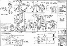
https://schematicheaven.net/marshallamps/jcm900_dualrev_50w_4500.pdf
https://schematicheaven.net/marshallamps/jcm900_dualrev_50w_4500.pdf
Attachments
Last edited:
Thanks rayma.
Wow, this drawings aren't made easy to read. That first one is just a blur, lol. The caps are probably overdue for replacement now that you mention it. Not sure if that would cause it or not.
The only maintenance I'm aware of (second owner), is that I had the reverb coil replaced by a tech when I bought it, before I had enough confidence to fix things myself.
I hear that the tracks lift off of the PCB very easily on these amps. Do you know the recommendated working temp for soldering? I Usualy work with 525-575.
Sorry , that applies to Stereo Hi Fi amps, where you have 2 fully separate and independent paths from input (say stereo stylus - DAC - whatever) to separate speakers.Seems like a power supply problem, since both channels do the same thing.
These are "Guitar amp switchable channels", completely different.
In fact there are no parallel channels at all, but different voiced Preamps, it´s a Mono amp end to end, starting with an common input and ending into single power amp and single cabinet (or more, but all in parallel), sharing A TON of things along the path.
At certain points, signal may go through certain path OR another, with different gain and/or EQ, in any case they never work together.
To boot , it uses a lot of switching dual Op Amps (M5201), think TL072 class, where either one or another is switched ON, separate inputs, common output, go figure, and of course both halves powered from same pins, let alone same rails.
Besides all those crisscrossing and switching paths, also many where signal travels through switches and connectors, including switching jacks which often become weak/dirty/corroded, and a couple board to board connectors.
It is a very complex amplifier; only way to repair it, specially a random signal loss problem,is to inject, say, 30mV 1kHz at the input and trace it up (with a scope) to speaker out, to find where it is lost.
Avoid random replacing parts (shotgunning) like the plague it is, it will only make things worse.
As a Friend, I suggest you clean it: a very very small squirt of good quality contact cleaner (not WD40) into every single jack (you have a dozen there) followed by plugging in-out so grime scratches and dissolves, same with every single pot, move them right-left end to end, etc.
Do not even PLUG your soldering iron.
You may get lucky and solve it by cleaning; if not, it´s *experienced* Tech time.
Thanks so much JMFhey. I do have an sencore analog scope. My tech retired, and I live in an area where we are unlikely to get another one that's worth his weight, lol.
I'm an Licensed Avionics Tech by trade, so I probably have the skills to fix this, I just don't have much experience with this type of equipment. Definitely a weak area.
I'll follow your advise and start with a good cleaning with some contact cleaner. I'll have a look once I'm doing that, and perhaps see something obvious (doubtful)
")
Awesome, Thanks so much! I never got a notice for your reply. perhaps a glitch with the new system here."....has anybody around here came up with a DIY attention circuit? Something like a power brake used to accomplish?"
Here's a good one that'll cost a LOT less than a commercially-available one:
Here is a thread (long one, before warned); where they make attenuation devices that are very good. Also, that forum has great Marshall people over there that are very friendly and willing to help.
https://www.marshallforum.com/threads/simple-attenuators-design-and-testing.98285/
https://www.marshallforum.com/threads/simple-attenuators-design-and-testing.98285/
I mounted an attenuator on the back plate of my 60W combo amp:

- The round thingy is a L-Pad attenuator similar to this
- The horizontal gold thingy is a 22 Ohms 50W resistor
- The 2 vertical gold thingies are 2.2 Ohms 50W resistors (in parallel)
Sorry, these should be 4.7 Ohms....
...
- The 2 vertical gold thingies are 2.2 Ohms 50W resistors (in parallel)
- Home
- Live Sound
- Instruments and Amps
- Marshall JCM900 4500