Guys ! Someone help me .. problem with biasing clone jcm800 50watt .. let’s start what I’m doing : connect 1ohm resistor from 8-1 pin both of el34 to the ground … I leave on standby the amp with the speaker connecting and the pots on zero … after 30 minutes I turn on the standby ,,,checking the pin 3 ( el34 plate ) and I wrote down 479 vdc ( I see the same with other el34 ) .. now I’m using this formula : 25/ plate voltage * 65% …for me is 0.0339 = 33-34 mV…. So I’m going and check the pin 1-8 and start to dial the trimpot ,, after 7-9 mV the speaker start makes a loud noise like (eeeeeeeeeeeeeee) …the one problem is this and the other problem is , the mV of pin 1-8 of one el34 it doesn’t the same with the mV of pin 1-8 on other el34 , like on first el34 is 6.5mV and on other is 2.4 mV , something like that .. and the el34 are matched ….where is the f&@ing problem !?!?! And here the schematic I use it ..Thank you

P.S. the amp works great , I check it on very low master volume . And the pre amp and the EQ works great but need to make the set the bias .
P.S. the amp works great , I check it on very low master volume . And the pre amp and the EQ works great but need to make the set the bias .


Not really, it should work anyway, and NO relation to sound you hear.
Please record a 30 second YT video showing it and link it here, (eeeeeeeeeeeeeee) is not very descriptive.
Also please confirm the exact schematic you used (post it here).
A picture of your build (one from above, another from below) will help.
You might have a grounding problem, lack of decoupling, improper layout, etc.
Thank you for help .. here is the schematic and the layout


Everything is correct and tight soldering .. I check all connections 4-5 times … but I don’t understand , everyone told me to change ( swap) the plate wires from O.T. …. I can understand if this change my problem because it’s the same wires …and how I have NFB?
I will send you the photos from inside of chassis when I return to home ..
Last edited:
In this post in an other thread you wrote about, and showed a provision to set the bias fast: https://www.diyaudio.com/forums/instruments-and-amps/376149-jcm-800-2204-marshall-mods-3.html#post6830261
The schematic in post #7 of this thread doesn't show this arrangement. In this hobby the devil often is in the details so could you provide a schematic that shows this provision?
In the other thread you wrote about this provision that in one position of the switch you could measure the plate voltage of the EL34, and in the other position you could measure the mV. I assume you measure the plate voltage of only one of the two EL34's, or? And what voltage in mV are you exactly measuring? According to the schematic the bias voltage is - 57 V so I don't understand how the "mV" fits in.
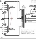
as for the switch it is only to show me indications and it works well .. look at the photo and you will notice that the red banana socket goes to one of the two central terminals and is divided as follows: one at pin 3 of a valve (el34 ) and the other on pin 1-8 of the same lamp and respectively the black banana socket goes to the second central terminal of the switch and is also divided into ground

let me tell you now what I noticed. so I took out all the valves, I turn on the amp and the speaker makes a hum again. I took out the HT fuse and measured the bias area.

let me tell you now what I noticed. so I took out all the valves, I turn on the amp and the speaker makes a hum again. I took out the HT fuse and measured the bias area.
1) they are NOT the same wires by any means; they are at OPPOSITE ends of primary winding, they are 180 degrees OUT OF PHASEt I don’t understand , everyone told me to change ( swap) the plate wires from O.T. …. I can understand if this change my problem because it’s the same wires …and how I have NFB?
2) follow wiring carefully.
NFB resistor network is 100k coming from speaker out terminals through a purple wire and a 4k7 resistor going to ground
They form a voltage 20:1 divider network (100k:4k7) feeding *some* speaker out voltage back (feed - back) into V3b grid pin 7, through a 100nF capacitor.
To work properly, it MUST be opposite-negative phase .
Names are not assigned at random or pulled out of the blue: NFB : Negative Feedback : Negative Feed Back.
Now it makes sense
")
But if OT primary wires are upside down, Negative becomes Positive, and your amp becomes an oscillator ... it will squeal more than a pig.
OK, I get the switch now. The black plug is connected to ground in both positions of the switch. The red plug connects either to the anode or the cathode of one of the EL34's.
Can the switch withstand the high voltages that will develop over it when the amplifier is used at high power levels?
Additional:
Only measuring one of the two EL34's when adjusting the bias could be a bit tricky if the EL34 that you don't measure passes more current than the one you are measuring.
Maybe for both safety reasons and to be able to measure both EL34's, you could connect the red wire that now goes to the anode of one of the EL34's with the cathode of the other EL34.
Last edited:
Swap the anode wires over, Red to White and White to Red. Sounds like the NFB is the wrong polarity.
For my surprise this is work !!! , I swap the O.T. primary wires and the oscillation disappear !!!.. now I have onotger problem
.. I must to dial the bias trimpot and reach the 33-35 mV… I finished the trim and it reached 20mV…I’m using 22kohm trimpot ,, if I change with 47kohm , can be reach 33mV?OK, I get the switch now. The black plug is connected to ground in both positions of the switch. The red plug connects either to the anode or the cathode of one of the EL34's.
Can the switch withstand the high voltages that will develop over it when the amplifier is used at high power levels?
Additional:
Only measuring one of the two EL34's when adjusting the bias could be a bit tricky if the EL34 that you don't measure passes more current than the one you are measuring.
Maybe for both safety reasons and to be able to measure both EL34's, you could connect the red wire that now goes to the anode of one of the EL34's with the cathode of the other EL34.
the switch is momentarly and will only be used to adjust the bias ..but also to be used (I mean, to turn right or left) if it does not load something in the banana socket there will be no problem
….. for this moment the amp is new and handmade. I definitely check it from below, and the 2 valves (el34)you are absolutely right about that and i know it .. i did this basically to make the adjustment to the bias faster and it looks more beautiful from the back regardless of whether it works or not ,, but i did not know that when we adjust the bias we have to put a resistor 1 ohm on the descent to get the settings ,, so anyway I will have to open the chassis to make the settings, therefore the switch will be removed .. end with this .. as for the bias setting that I can not reach the 33mV I will fix it today ,, something last now .. as I had mentioned as soon as I turn on the amp there is a low hum in the speaker σα I disconnected the NFB cable to see if it still does, but I did it again .. also when it is in HT operation (standby off). hum does not increase with the master volume but decreases more as soon as I set the presence to 10….
I wonder what is going on with the bias trimpot.
Yesterday you wrote in one of your other threads that you had a 50K trimpot installed instead of the 22K as per schematic and asked if that could be a problem. See: https://www.diyaudio.com/forums/instruments-and-amps/379006-diy-hot-mod-v2-3.html#post6842775
About one hour earlier in this thread you wrote in post #13 that you are using a 22K trimpot for bias and asked if changing it to a 47K trimpot would make it possible to set the voltage (over the 1 Ohm resistor) at 33 mV.
So yesterday you changed the trimpot from 22K to 50K?
Last edited:
I was wrong. From the beginning I had a 22k trimpot. look there is a difference between schematic and layout in some values like the ones I show in the photo…

whenever today I bought the right resistors and I will change them in the afternoon ..logically I will have better measurements ..hope
whenever today I bought the right resistors and I will change them in the afternoon ..logically I will have better measurements ..hope
I so happy guys .. I change those wrong value resistors and the trimpot ( post #18) and set the bias without any problem ..and remove the 2x 1ohm resistor and grounded the 1-8 pin both el34 …. Test the amp on my celestion g12 rockdriver vintage and the sound it’s awesome!!!!!!!!!!… only to do is test on max level .. today I’ll try…..thank you guys for everything .. best regards .. by the way , as far as the problem with hum when I turn on the amp after 4-5 min disappear …but ok ��
.. today I’ll try…..thank you guys for everything .. best regards .. by the way , as far as the problem with hum when I turn on the amp after 4-5 min disappear …but ok ��I forgot to say that there is a difference in the cathode of el34 between them… I had to set the bias to 35.6mV. whenever one valve is at 35.6 mV and the other at 40.1mV. there is a difference of 4.5mV, ie 13%….. el34 are jj matched, but I bought them used. whenever I do not know what use and amount are overworked .. I also saw in a forum someone say that in matched output valves the allowable limit on the cathode is 20% between them..
- Home
- Live Sound
- Instruments and Amps
- Set bias on clone jcm800 help