Hello guys, my first attempt at guitar amps. I'm repurposing an old Hammond power tx from previous valve projects. The issue is, it is a 500-0-500vac tx (200ma), so awkward for anything guitar amp but it's what is in the parts bin so it's what's going to be used.
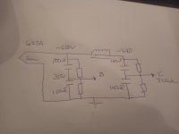
Looking at it, I can get the voltage down to around 330v-350vdc resistively and generate a bit of heat. Drop it down with a choke input, but the chokes I have for that are massive and heavy... I was going to go for resistance then realised I was going to have to stack two caps for the reservoir. This is when I thought about, why not just take the B+ from the junction of the two caps (parallel resistors to each cap to balance and also as drain) to get me in to ~330vdc.
Then, as I've been reading about 'power scaling', another brain fart, could I not just stack 4 caps at the input and use a switch to tap the dividers for different voltages rather than use a MOSFET (and the bother of heatsinks for the chassis) to scale the output power?
Thinking out loud at well past bedtime...
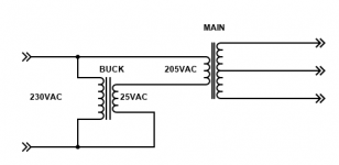
Won't work, use a bucking transformer instead. This example reduces the secondary voltage by by 10%.
The current capability remains the same.
Choke input filter is an alternative for reducing the voltage also, if it is adequately rated.
The current capability remains the same.
Choke input filter is an alternative for reducing the voltage also, if it is adequately rated.
Attachments
Last edited:
Do what Hammond did. Very heavy choke and oil capacitors. (I hope you saved them; they are costly to buy.)
As Rayma says, you can't pull DC from a capacitor "divider". Bucking is good for 10% maybe 20% but 50% is getting silly (your bucker is half the size of your main). 700V, 630V, 560V maybe; still way more than any sane guitar amp.
Lots of things are too big to throw away but two awkward to use. (I've filled a dumpster this year.)
Thanks guys. In the cold light of day I can see now It wasn't going to be as straight forward as I imagined.
I can sell it, but the 'parts bin problem solving' is part of my exercise to learn more about electronics. I enjoy this part than drilling the chassis lol.
The plan is single ended with an el34 in triode/ultralinear based on the OPs on Tubelab's site originally. If I could've dropped the voltage simply and efficiently, then it would've been pentode at ~300v based on the datasheet OP.
Do what Hammond did. Very heavy choke and oil capacitors. (I hope you saved them; they are costly to buy.)
As Rayma says, you can't pull DC from a capacitor "divider". Bucking is good for 10% maybe 20% but 50% is getting silly (your bucker is half the size of your main). 700V, 630V, 560V maybe; still way more than any sane guitar amp.
Lots of things are too big to throw away but two awkward to use. (I've filled a dumpster this year.)
Quote:
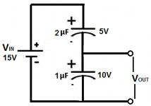
Capacitive DC Voltage Divider Circuit
Voltage is divided up in a capacitive DC voltage divider according to the formula, V=Q/C. Therefore, voltage is inversely proportional to the capacitance value of the capacitor. So, the capacitor with the smaller capacitance will have the greater voltage, and, conversely, the capacitor with the greater capacitance will have the smaller voltage.
Below is an example:
Capacitive DC Voltage Divider
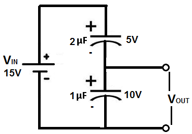
The supply DC voltage in the above circuit is 15V. This means that this 15 volts will be divided across both capacitors so that the voltage dropped across them both will equal to the 15-volt supply source. Assuming both capacitors hold the same charge, Q, the voltage can be calculated just from the capacitance values of both components. Being that the the 2μF capacitor is twice the value of the 1μF capacitor, it will have one-half the voltage. Therefore, the 1μF capacitor will drop 10 volts across it, while the 2μF capacitor will drop 5 volts across it.
End quote.
What am I missing? Why can't I pull DC? I'm not an engineer so it might be very obvious.
The series caps as reservoir will amount to 50uf that the GZ34 will see and will be within what the rectifier can handle. I thought maybe I could tap it both sides of a choke for plate and screen. Seemed too good to be true so I'm just asking for my own understanding. Thanks
Attachments
> Quote: Capacitive DC Voltage Divider Circuit
Please say where you get such teachings. In this case I found it on one of the explanatory sites that everybody knows, which does not mean they are right.
Possibly this one. Capacitive Voltage Divider
"DC" is a long-term condition. Long-term, the average current in a capacitor sums to *zero*. This is why we use capacitors to block DC from speakers. This is why a cap across a power supply does not heat-up and die.
Their proposed solution is valid for the instant that the battery is connected.
Yes, 15V DC applied to 2u and 1u in series will split 5V and 10V. At first. Any load will bleed it to zero. Using 1Meg as a sim "meter" it will bleed in a second. The several-K equivalent load of a power amp will bleed faster than you can blink.
There are, as always, more complicated ways to connect more parts and find a different result. Four electronic switches working at fast rate could change the 1u to 700V and dump that to the 2u for 350v. (Some choke would be needed to avoid infinite current spikes.)
Attachments

What am I missing? Why can't I pull DC?
That example shows the conservation of charge. When you remove charge by connecting
resistor loads, the charge is no longer conserved, so that explanation no longer applies.
The parallel resistors determine the DC voltage drop, not the capacitors.
Last edited:
You can pull dc current with the two paralleled resistors in place (or even with only the upper resistor in place) but the dc-current only flows through the resistors. Nothing except for the ripple current, which is an ac voltage superimposed on the dc voltage, flows through the capacitors. So you wind up were you started: This arrangement produces pretty much the same amount of heat as a 'normal' dropper resistor would. It is as if you would put a capacitor parallel to the dropper resistor. And if the amplifier you want to build is not a pure class A amplifier, than the regulation with such large dropper resistors will be very poor (you will have a lot of 'sag').
You could use a choke input filter like others already suggested. That will reduce the voltage substantialy compared to using a capacitor input filter (estimation: with about 180 V). The regulation of this type of filter is pretty good. On page C of this datasheet for the GZ34 (= 5AR4) you can see what voltages you roughly can expect at different current draws:https://frank.pocnet.net/sheets/030/g/GZ34.pdf
If you would use solid state rectification, than the voltages will be somewhat higher (estimation: about 20V) because the resistance of tube rectifiers is higher than that of solid state rectifiers.
Hello guys, my first attempt at guitar amps. I'm repurposing an old Hammond power tx from previous valve projects. The issue is, it is a 500-0-500vac tx (200ma), so awkward for anything guitar amp but it's what is in the parts bin so it's what's going to be used.
Looking at it, I can get the voltage down to around 330v-350vdc resistively and generate a bit of heat. Drop it down with a choke input, but the chokes I have for that are massive and heavy... I was going to go for resistance then realised I was going to have to stack two caps for the reservoir. This is when I thought about, why not just take the B+ from the junction of the two caps (parallel resistors to each cap to balance and also as drain) to get me in to ~330vdc.
Then, as I've been reading about 'power scaling', another brain fart, could I not just stack 4 caps at the input and use a switch to tap the dividers for different voltages rather than use a MOSFET (and the bother of heatsinks for the chassis) to scale the output power?
Thinking out loud at well past bedtime...
Hi,
What about using a tube rectifier and end with(probably) something around 400/450Vdc at the output.
The tube rectifier "drops" around 20+ volts just to do the rectifying... Of course if the transformer has a heating winding, dedicated to only heating the tube rect.
Using semiconductor rectifiers you get a much higher Vdc.
If you decide to go tube rectifier, then pay utmost attention to the maximum allowable smoothing capacitance for a particular selected tube rectifier.
Tube rectifiers don't like current peaks while charging electrolytics every single half period of the incoming ac...
Wish you luck.
On the valve amp this used to be powering, I used a GZ37 or GZ34, only ones I have that will handle the 500v as a single rectifier, and adjusted the input cap value to get the B+ I wanted. From the planning of this older amp, only choke input would bring it to 400-450v range as I remember. I'll have a look with psud again. Thanks.
- Home
- Live Sound
- Instruments and Amps
- Power supply Cap voltage divider