Hi all, first post here! I have 2 x Behringer EP4000's driving 8x18" subs in an infinite baffle system for my home cinema.
I have had them up in the attic for 4 years now, they are remotely powered when the receiver is powered up.
Recently i noticed i wasn't getting the usual 'ompf' that i used to, and ventured up there to see what's going on. Both amp's integrated breakers had tripped. On switching them, they would both buzz and trip off again.
So, I've pulled one out of the loft and via a process of elimination discovered the channel one is causing the tripping of the breakers.
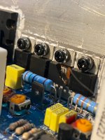
I pulled that board out for closer inspection and discovered T16, a 50N06 had blown its top.
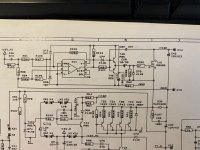
I have found a schematic online but don't pretend to know exactly what i am looking at here. I can replace the 50N06, but is there anything else it would be worth testing and upgrading while in there? I will pull the other amp out of the attic, but i suspect that as both went at the same time, it will have the same issue.
Thanks for any advice")
Steve
I have had them up in the attic for 4 years now, they are remotely powered when the receiver is powered up.
Recently i noticed i wasn't getting the usual 'ompf' that i used to, and ventured up there to see what's going on. Both amp's integrated breakers had tripped. On switching them, they would both buzz and trip off again.
So, I've pulled one out of the loft and via a process of elimination discovered the channel one is causing the tripping of the breakers.
I pulled that board out for closer inspection and discovered T16, a 50N06 had blown its top.
I have found a schematic online but don't pretend to know exactly what i am looking at here. I can replace the 50N06, but is there anything else it would be worth testing and upgrading while in there? I will pull the other amp out of the attic, but i suspect that as both went at the same time, it will have the same issue.
Thanks for any advice
Steve
Attachments
Last edited:
That is the rail switch that blew out. If that was the only thing that shorted, the amp would still *work*, but overheat in seconds at high power. In order to cause the breaker to trip either T19-T22 or D30 would need to be shorted. If any one of T19-22 is bad you would change them all (use the Fairchild version, they are the only ones you can trust nowadays). There may be other collateral damage. Check the driver transistors and the bias stack as a precaution any time you go fixing an output stage.
Running an amp up in the attic where it is hot reduces the thermal margin. Are you running bridged 4 ohms? MTTF at full power 2 ohms per channel is about 50 cumulative hours at “normal” temperatures, and of course gets cut in half every 10C.
Running an amp up in the attic where it is hot reduces the thermal margin. Are you running bridged 4 ohms? MTTF at full power 2 ohms per channel is about 50 cumulative hours at “normal” temperatures, and of course gets cut in half every 10C.
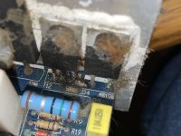
Thanks, wg-ski, All T19-T22 are short circuit B-C-E in all directions and T23-T26.
In comparison to the other channel, which are all resistive.
There's charing around T12 on the other channel though...I probably need to pull a few of these out to properly check them before considering them ok
Cheers
steve
In comparison to the other channel, which are all resistive.
There's charing around T12 on the other channel though...I probably need to pull a few of these out to properly check them before considering them ok
Cheers
steve
Attachments
Meanwhile on amp 2.
I the fault seems to be different on this one. I isolated each channel in turn and even with both disconnected from the psu board, the breaker tripped.
Then I disconnected the transformer outputs from the board and no tripping. It looks like there is one diode of one bridge rectifier that is closed circuit both ways. Hopefully that’s the only fault on the one. To test I I may have a meaty BR somewhere I can plug in temporarily…
Bridge rectifiers are another common failure. That could be the only thing wrong. Change it out, then bring the amp up on a dim bulb limiter. With the other one, check everything that could potentially go out if both the rail switch hexfets and the output transistors have shorted. Again, bring it up on a dim bulb initially, which will let you catch anything you missed before you blow it up again.
One big thing that could be missed is having one or both of the rail switches permanently stuck ON. The amp would *work*, but run extremely hot and be easy to burn out due to running the output transistors too hard. That is a potential cause of the original failure - it would rapidly accelerate the normal wear out mechanism I described above. You would have seconds or minutes. Verify that these are working again with a light load on the amp (say, 1K ohm) before proceeding with a normal load. I’ve had the *opposite* problem with an EP2500 - a rail switch that refused to turn ON, making the amp clip at about 150 watts. At least that’s safe for it.
One big thing that could be missed is having one or both of the rail switches permanently stuck ON. The amp would *work*, but run extremely hot and be easy to burn out due to running the output transistors too hard. That is a potential cause of the original failure - it would rapidly accelerate the normal wear out mechanism I described above. You would have seconds or minutes. Verify that these are working again with a light load on the amp (say, 1K ohm) before proceeding with a normal load. I’ve had the *opposite* problem with an EP2500 - a rail switch that refused to turn ON, making the amp clip at about 150 watts. At least that’s safe for it.
Thanks for the advice.
Amp 2
I am not sure if i have a man enough BR to hand, so may swap the PSU board over from the other amp so i have at least one functional. What do you mean by bringing it up on a dim bulb limiter though?
Amp 1
I suspect i need to pull off the board all the chips on the heat sink and test individually, and also test for any obvious other shorts or charing. I can check diodes in situ i suspect.
What do you mean by having the rail switch stuck on...how can i check for this? sorry for the newbie amateur questions!
Steve
Check voltages at X13 and X20 with respect to X12. They sit at +/-55volts in the normal state, and switch up to the 110 volt rail when you ask for enough signal to need it, and only when you need it. If they sit stuck at the 110 volt state, it is dangerous to run the amp with a heavy load (even 8 ohm, but ok for testing with a VERY light load). If they are “stuck” there is something wrong with the driver circuit for it and would need to be corrected. If you remove the mosfet switches entirely, the amplifier will function normally, up to about 150 watts in 8 ohms - same as just running off a regular +/-55 volt supply. That is one intermediate step that can be verified when repairing a dead channel.
Ok will do that, once i have the new BR in.
I have swaped the chanels from amp two to amp one to use the PSU from that unit and no bang so far. I let it run for a few mins and the left channel's heat sink, as viewed from the back of the device, was getting hot with no signal, so definatly something else up with these chanels that could of caused the BR diode to go short. Or the other way round.
Cheers
Steve
Ok, back off me jollies.
The blown open component on amp 1 was a mosfet from the class H comparator circuit. The one on the opposite phase was short s-d.
The diodes between e-c on the output transistors were also closed circuit. The driver transistors test out fine on both sides. But all outputs are blown. I presume the compareter drove the channel at full voltage one side and caused it to overheat and pop? Will keep testing, see if anything else is amiss. Any suggestions what else I should consider?
Steve
Are you running bridged 4 ohms? MTTF at full power 2 ohms per channel is about 50 cumulative hours at “normal” temperatures, and of course gets cut in half every 10C.
I am running 2 x 18" woofers in each of the 4 large IB manifolds. Each woofer is 4ohm, so i have the two per manifold in series to make 8ohm, powered by one channel of the EP4000. So, 2 manifolds to each EP4000.
Hope that makes sense. I plan on drastically improving the fan situation to these as it does get hot up there!
With just an 8 ohm load per channel, it would take a lot to make the amp fail. The kind of damage you describe is what happens when a DJ runs two subs in parallel in bridge mode and turns it up to 15 night after night for a month. To generate that kind of heat with a relatively light load would take a very hot attic and I doubt anything would survive. Once it is fixed, you’re going to have to find somewhere cooler to run it.
If the entire power stage is shot, I would put it back together slowly and methodically. Leave the hexfets switches on the comparator circuit OUT initially, and try to get it working off the low rails. If they are stuck ON, then you can determine that (and correct it) before proceeding with full rail voltage.
If the entire power stage is shot, I would put it back together slowly and methodically. Leave the hexfets switches on the comparator circuit OUT initially, and try to get it working off the low rails. If they are stuck ON, then you can determine that (and correct it) before proceeding with full rail voltage.
Ok, I been poking around in side and discovered the fan had failed. 24v present but no spinning at all. Fan tests open circuit. So, she got very hot I assume.
On the other amp, with the working psu and and no obvious blown channels (but one gets hot the other stone cold with no signal) I tested the rail you mentioned and all looks fine, 57v présent on both sides of both channels.
I have always wanted an oscilloscope, so today ordered one along with a signal generator and dummy load.
I would put in some thermal protection.Ok, I been poking around in side and discovered the fan had failed.
Doesn't make sense, just using airflow. It should also shut off in case of overheating.
Put a mains voltage fan, more reliable.
Low voltage DC fans have a squirrel cage AC motor inside, and a circuit to generate AC from DC, that often fails.
AC fans are more reliable, and put a ball bearing type fan.
As a bonus, air flow may be higher.
And of course a thermal fuse too.
Low voltage DC fans have a squirrel cage AC motor inside, and a circuit to generate AC from DC, that often fails.
AC fans are more reliable, and put a ball bearing type fan.
As a bonus, air flow may be higher.
And of course a thermal fuse too.
Connect the fan to supply after checking polarity, sometimes the sleeve bearing dries out and motor sticks, happens in computer SMPS all the time.
And due to the circuit inside, the working fans also test open at times, which is why I said connect to supply, never if dead short.
Can be lubed, just check it is not stuck.
But I would not consider it reliable away in the attic, change all the fans, including the working one to AC supplied fans, they are cheap.
It sounds to me like the semi working amp is over biased. Check make sure R109 (thermistor) isn’t open circuit. I’ve had this happen on old QSC’s and cause them to run blistering hot. You could adjust VR6 to compensate, but the bias will have the wrong tempco. Heck, it could just be the pot wiper is open. It sounds like it is ultimately fixable.
The dead fan is definitely the problem with the really dead one. It may have been bad a long time, accelerating the heat death. Explains it fully. Those DC brushless fans just don’t last that long, and a budget amp isn’t going to use a really good one. Either install some sort of fail safe or use an AC fan. Those will go until the bearings are just too shot for it to start up.
The dead fan is definitely the problem with the really dead one. It may have been bad a long time, accelerating the heat death. Explains it fully. Those DC brushless fans just don’t last that long, and a budget amp isn’t going to use a really good one. Either install some sort of fail safe or use an AC fan. Those will go until the bearings are just too shot for it to start up.
There are life expectancies for fans when you read the datasheet. I don't think its whether its AC or DC its the quality of the bearings and the other components. The ones in there are most likely budget. Hope you find all the blown devices before repower. I don't know if you can add some series resistors to the amp from the supply to make you life easier.
Last edited:
The issue is reliable cooling...
If AC is available, use it.
Silly to convert to low volts DC, and the fan makes it AC again.
And if you open those fans, you will find hardly any space in the hub where the circuit is installed.
There may be some legal or safety issue, but I would prefer a simple coil moving the fan off mains.
Good fans last about 10 years 24x7 before needing maintenance, good enough for a $4 item.
- Home
- Live Sound
- Instruments and Amps
- Behringer EP4000 gone pop x2