I have two Music Man RD-50s ('81 RevA and '82 RevB) and both of them either have, or have had, problems with the output sections, namely red-plating tubes. From what I've found on the various forums, it looks like a fairly common issue, and often seems to only affect one side of the pair. In one post on another forum the guy was actually seeing significant (~2x) variation in idle bias current between the two tubes but eventually decided it must be normal.
The red-plating problems usually get 'fixed' by replacing Q3 & Q4, the 30v Zener (D9) and/or a diode or resistor or two, but in at least one post on another forum the tech said it was the second time the amp had come in for the same issue. The recommendation was to upgrade the power rating on the zener and screen resistors, but I have my doubts that this isn't just masking another problem.
As for my RD-50s, previous owners/techs apparently tried to address the output section problem on both of them too. The stock 30v zener (D9) in the '82 RevB was replaced at some point with a 1N3030 27v zener, and the 470 ohm R62 was replaced with 560 ohm resistor.
The '81 RevA came to me with two 470k resistors installed from cathode to ground on V2 and V3 - or from collector to ground on Q5 and Q6 - depending on how you look at it. (This fix is mentioned in a factory repair bulletin, but was to address temperature-related "instability or output glitches" due to a "change in design characteristics of the Philips ECG tubes" with double top getters, and was recommended only for the 65, 75 and 100 Watt versions.)
A lot of people blame the high plate voltage, too, but they're 'only' 580v or so, while my Model 75 runs at near 700v and I've had the same pair of Sylvania 5881s in it for years and play it regularly, and I've never had any issues. In fact, they still test NOS! Sorry, I'm not buying the high plate voltage thing...
So, my big question here is, does anyone have any novel ideas about how to really make these things more reliable? Along the lines of the "immortal amp" concept, there's gotta be some good ideas out there for making these things hold up better...
I never found them unreliable. I did service my share of them over the years, but there just isn't a brand or model that never fails.
Stop trying to find patterns in a small number of repairs.
Tubes fail. Power tubes short and what do you know, it takes out the cathode transistor. Is this common? Not particularly. When power stage failures occur, do they usually take out the transistors? Sure, just like a million Fender amps that burn up the 470 ohm screen grid resistors when the tube fails.
I fixed a couple of these back in the 80's, and it did look like the high B+ had something to do with the failure, bit this was in the heat and humidity of south Florida, and less than ideal operation conditions.
Ever see a 6L6GC with the black base carbonized to destruction due to an arc inside the base of the tube from pin 3 (plate) to pin 2 (grounded heater).
Moisture + dust and dirt + high voltage + accumulated cigarette smoke = fried parts. The brown glue used to glue the glass tube into the base can accumulate all of the above until breakdown occurs.
Yes, I have seen the same thing in other amps, used in hot dirty clubs, or repeated outdoor gigs, but sometimes the amp itself drank a bit too much beer.
An SVT running hard when the speakers blow (open voice coil) will fry in the same manner, and the arc ate up the OPT too.
Statistically they ARE incredibly reliable.
Not "a very common issue" by any means, specially because MM TIGHTLY controls tube plate current, way more than in *any* conventional tube amp.
If anything, current tubes are not up to par to what MM fit 40 years ago, but that´s not MM´s fault, they designed amps basd on high quality tubes easily available way back then.
Same happens with old Marshalls some of which used incredibly high +V but even there MM is more reliable by comparison.
In fact, unless I see and measure it myself, I´d label it "impossible", go figure.
FWIW those are cascode/totem pole power stages, and tube current (idle or signal) does NOT depend on the tube at all, it can only pass whatever the individual driver transistor feeds it.
Tube and transistor are in series, and Kirchhoff´s Law applies (of course).
Not "a very common issue" by any means, specially because MM TIGHTLY controls tube plate current, way more than in *any* conventional tube amp.
If anything, current tubes are not up to par to what MM fit 40 years ago, but that´s not MM´s fault, they designed amps basd on high quality tubes easily available way back then.
Same happens with old Marshalls some of which used incredibly high +V but even there MM is more reliable by comparison.
No, not normal at all.In one post on another forum the guy was actually seeing significant (~2x) variation in idle bias current between the two tubes but eventually decided it must be normal.
In fact, unless I see and measure it myself, I´d label it "impossible", go figure.
FWIW those are cascode/totem pole power stages, and tube current (idle or signal) does NOT depend on the tube at all, it can only pass whatever the individual driver transistor feeds it.
Tube and transistor are in series, and Kirchhoff´s Law applies (of course).
Thank you all for the insights! Sr. Fahey's observation that MM controls tube plate current way more than conventional amps - and that OP tube current does not depend on the tube - is kinda why I'm convinced that the problems I'm seeing are due to a weak link in the SS part of the output circuit. Possibly thermal? Maybe transistor insulators?
FWIW, I've replaced my share of fried components due to tube failure in conventional amps, especially from shorted beam tetrodes. But these amps seem to be frying the tubes, not the other way around...
I'm starting to get how these MMs work, and my Model 75 has been super reliable and the Sylvania 6L6GB/5881's are still fresh as new after 100+ hours of operation (even though I'm "supposed" to be running GCs in it). I'd like to get similar mileage from these RD-50s and not be afraid to run some $$ NOS STRs or EL-34s in it.
So, while it would be nice to eventually find a "weak link" causing these issues with the RD-50s, in the meantime I'm hoping there's some reasonable way to protect the tubes from upstream failure(s). I'm especially curious as to what role the screen voltages play in a cascode power stage...
Ok, lost my hard disk with thousands of schematics but found this RD50 at Elektrotanya.
Cropped only the power stage for clarity:

The normal way:
1) a normal tube passes all the current it can (say 200-250mA, check datasheets) with 0V at the grid.
Even more if grid is Positive, only that´s not common because now it will "eat" grid current and a normal PI can´t supply more than 1 or 2 mA, tops which is not much.
2) so normal amps apply +V to plates, a quite high voltage to screens (250V to 400V) BUT negative voltage to grids (-35 to -55V) so they are "throttled" , or "under control" and then they pass relatively low "idle" current.
3) Signal voltage is applied to grids, cathodes are grounded, and grid to cathode voltage variation modulates plate current.
The Musicman way:
4) Grids do NOT receive signal and in fact are fixed biased Positive (+30V)
To boot, low impedance Bias supply can give them "all the current they ask for"
Screens are still receiving a high Positive voltage (here +290V) so tube is TURNED ON , BIG TIME, way more than by "just" getting 0 V at grid (which is "maximum" in a conventional amp).
5) so why don´t tubes *explode*????
Because their cathodes are not straight grounded but through series transistors and *they* control how much current goes through, say some 15-20mA , quite "cold" biasing.
6) but ... but .... don´t very cold biased tubes sound "ugly - cold - choppy"?
True ... if *they* decide how much current will pass, because grid curves (check it on datasheet) are quite non-linear at high negative voltage (more than -50V) or very low currents (same thing) but here series transistors rule, and transistors are very linear at low currents, so .....
7) notice both circuit halves, top and bottom are fully symmetrical, one exactly mirrors the other:
* Top: from IC4a to V2 and everything in between.
* Bottom: from IC4b to V3, same thing.
Only "difference" and which actually guarantees "mirroring" is that IC4b is connected as a "unity gain inverter", its output is exact same as IC4a but out of phase.
That´s why I said "impossible" ... obviously in a properly working Op Amp + Transistor driver (Tubes don´t have much say in this) and only way for it to be different is for parts values being different (poor repair?) , including some driver transistor not being up to the task.
JE1692 are hard to impossible to find, they are somewhat unusual, (they have very high current gain and stand 100-120V and if blown, not easy to substitute.
Impossible in Argentina, I have successfully used TIP 41C, just buy 10 of them and pick the two with highest current gain,I can always use the other.
So you *might* have just one driver transistor replaced , or both but unmatched and/or barely suitable or don´t stand required 100-120 Vce
TIP41C does, just pick best of the bunch.
Buy them at Mouser - Digikey - Farnell , FORGET EBay, Alibaba, etc.
And any J1692 offered today is highly FAKE supect.
To boot, notice there is no bias adjustment, MM probably chose parts values so they "self bias" ... IF you use the proper parts that is.
Cropped only the power stage for clarity:
The normal way:
1) a normal tube passes all the current it can (say 200-250mA, check datasheets) with 0V at the grid.
Even more if grid is Positive, only that´s not common because now it will "eat" grid current and a normal PI can´t supply more than 1 or 2 mA, tops which is not much.
2) so normal amps apply +V to plates, a quite high voltage to screens (250V to 400V) BUT negative voltage to grids (-35 to -55V) so they are "throttled" , or "under control" and then they pass relatively low "idle" current.
3) Signal voltage is applied to grids, cathodes are grounded, and grid to cathode voltage variation modulates plate current.
The Musicman way:
4) Grids do NOT receive signal and in fact are fixed biased Positive (+30V)
To boot, low impedance Bias supply can give them "all the current they ask for"
Screens are still receiving a high Positive voltage (here +290V) so tube is TURNED ON , BIG TIME, way more than by "just" getting 0 V at grid (which is "maximum" in a conventional amp).
5) so why don´t tubes *explode*????
Because their cathodes are not straight grounded but through series transistors and *they* control how much current goes through, say some 15-20mA , quite "cold" biasing.
6) but ... but .... don´t very cold biased tubes sound "ugly - cold - choppy"?
True ... if *they* decide how much current will pass, because grid curves (check it on datasheet) are quite non-linear at high negative voltage (more than -50V) or very low currents (same thing) but here series transistors rule, and transistors are very linear at low currents, so .....
7) notice both circuit halves, top and bottom are fully symmetrical, one exactly mirrors the other:
* Top: from IC4a to V2 and everything in between.
* Bottom: from IC4b to V3, same thing.
Only "difference" and which actually guarantees "mirroring" is that IC4b is connected as a "unity gain inverter", its output is exact same as IC4a but out of phase.
That´s why I said "impossible" ... obviously in a properly working Op Amp + Transistor driver (Tubes don´t have much say in this) and only way for it to be different is for parts values being different (poor repair?) , including some driver transistor not being up to the task.
JE1692 are hard to impossible to find, they are somewhat unusual, (they have very high current gain and stand 100-120V and if blown, not easy to substitute.
Impossible in Argentina, I have successfully used TIP 41C, just buy 10 of them and pick the two with highest current gain,I can always use the other.
So you *might* have just one driver transistor replaced , or both but unmatched and/or barely suitable or don´t stand required 100-120 Vce
TIP41C does, just pick best of the bunch.
Buy them at Mouser - Digikey - Farnell , FORGET EBay, Alibaba, etc.
And any J1692 offered today is highly FAKE supect.
To boot, notice there is no bias adjustment, MM probably chose parts values so they "self bias" ... IF you use the proper parts that is.
Wow! Super interesting... This is starting to make more sense and I'm sure I'm not the only one who will benefit from this explanation. Sorry about your hard drive, I should have posted a schematic right from the start.
And, thanks to your very informative deep dive on another forum a few years ago regarding replacement drivers (thank you again), I plan to run the MJE15030 transistors that Mr. Enzo recommended.
So, Am I understanding correctly that in the MM cascode design the screens perform the same function as they do in conventional layouts, i.e., limiting the tube's maximum plate current?
I'm also curious about MM's recommendation in their service bulletin that I mentioned in the first post: What would be the practical effect of placing a 470K resistor from cathode to ground?
Here's the link to the schematic I neglected to post earlier:
https://el34world.com/charts/Schematics/files/Musicman/Musicman_1650rd.pdf
...Am I understanding correctly that in the MM cascode design the screens perform the same function as they do in conventional layouts, i.e., limiting the tube's maximum plate current?....
No. They cause current to flow. If at zero re: cathode the tube is cut-off.
Yes, at higher voltage there is some limit to current.
Also note that they run 300V G2 while plate is at 600V. Many-many audio amps run G2 near plate for system simplicity. Extreme amps raise the load impedance and the plate voltage. Because dissipation is still limiting, you can't use all the current you get at a high Vg2, so use a low Vg2 for low G1 drive and low G2 current. Also low plate saturation voltage (pencil 1/5th of Vg2).
BTW there are several variations of the MM power stage, with different thoughts behind them.
The one in #6 here may be analyzed: R68 R50 make a 110:1 divider. Then Q3 reflects and multiplies R51 as about 750 Ohms. It should idle-bias like an equivalent 750r cathode to ground. With the +50V at G1 the idle bias should be very stable (if the Silicon don't go soft). Signal wobbles the equivalent resistor up toward 1,500r and down toward zero, making signal current.
The 470k service note smells like a waved dead chicken to me. I have wondered what over-voltage is possible on these transistors. I don't think 470K makes a bit of difference here. 1mA at 500V? If something here kicks to 500V then it has more than 1mA behind it.
Last edited:
Of course.
Cathode voltge will swing between , say, 80-100V at very low idle, near cutoff (should check thatasheets but guess I´m not too far) to, say, some 10-20V (so net positive grid voltage is +10/+20V , always with reference to +30V bias) but if anything above 120V appears at Cathodes/transistor collectors then tubes are giving up the ghost or straight arcing/shorting.
Agree that a 470K resistor across drive transistors won´t do much, if at all.
MAYBE they are there for another reason: if drive transistor OPENS now floating cathode voltage does not go trough the roof, maybe there is some reverse cathode-grid voltage limit which must not be crossed or something of that sort.
Just speculating here and only because it came from MM who should know, if it were only "Internet lore" I would plain discard it.
...................it came from MM who should know, ....
Remember that a big reason MM was still messing with tubes is that Fender and Peavey had introduced transistor amps and had had notorious reliability troubles. Lab-bench audio power amps looked mature but transistor stage amps gave trouble for years. Stage amps don't stick to a "load line" but smack the envelope every which way. Second breakdown went from unknown to known and then worse (with planar parts). Falling prices encouraged more-transistor designs which oscillated irreproducably with build and load.
Peavey resorted to hiring Sondermeyer away from RCA Somerville. Jack wrote most of RCA's app-notes, not knowing how we abuse amps. Peavey taught him. Hartley and Jack made a good team. I don't know who on MM's team had Jack's depth of transistor understanding.
Thank you everyone for the incredibly credible and informative information you've shared so far, what a great resource this is!
Ahh yes, PRR! The old dead chicken waving routine... better maintenance through esoteric rituals!
Here's what it says in the service bulletin:
Note that it says this applies to all 6L6 MM amps at first, but doesn't specify the 50W version at the end, and as PRR points out, the 1650-RD chassis/RD-50 design is a bit different. Attached is a shot of the 75W (Model 75) output section for comparison.
Questions:
Does the factory 470k mod maybe make more sense in the 75W circuit? If so, what would be the corollary resistor value in the 50W circuit?
Also looking at the 75W version, I'm curious as to what D15 & 16 do. If they're protecting the plates from excessive current, maybe I should consider something similar on the 50 Watt version?
And to Sr. Fahey's comment that assured tube destruction will result if more than 120V appears at the Cathodes/transistor collectors on the 50W version, are there any suggestions on how to prevent 100+V or so from getting to this point in case of an upstream component failure?
Ultimately, I'm hoping there's a strategically placed component or two that will provide an extra margin of protection for NOS output tube$...
Ahh yes, PRR! The old dead chicken waving routine... better maintenance through esoteric rituals!
Here's what it says in the service bulletin:
This applies to all Music Man amps requiring 6L6GC tubes. Due to a change in design characteristics of the Philips ECG tubes, some Music Man amplifier models show signs of instability or output glitches when using these tubes... identifiable by the double getter arrangement on the top of the electrodes. The instability usually will occur at an input frequency of approximately 70 to 150 Hz as you approach full output. The instability is temperature related and the tubes must warm up approximately 2 to 3 mins. The glitches occur anywhere on the wave and are not to be confused with crossover distortion when the output begins to clip, or preamp popcorn noise.
To eliminate the problem, solder a 470k 1/4W resistor from pin 8 to pin 2 on the 6L6 tube socket. Install one resistor for each push/pull pair in 150 watt versions and one resistor per socket in 65, 75 and 100W versions.
Note that it says this applies to all 6L6 MM amps at first, but doesn't specify the 50W version at the end, and as PRR points out, the 1650-RD chassis/RD-50 design is a bit different. Attached is a shot of the 75W (Model 75) output section for comparison.
Questions:
Does the factory 470k mod maybe make more sense in the 75W circuit? If so, what would be the corollary resistor value in the 50W circuit?
Also looking at the 75W version, I'm curious as to what D15 & 16 do. If they're protecting the plates from excessive current, maybe I should consider something similar on the 50 Watt version?
And to Sr. Fahey's comment that assured tube destruction will result if more than 120V appears at the Cathodes/transistor collectors on the 50W version, are there any suggestions on how to prevent 100+V or so from getting to this point in case of an upstream component failure?
Ultimately, I'm hoping there's a strategically placed component or two that will provide an extra margin of protection for NOS output tube$...
Attachments

Interesting observation PRR - maybe there's something in the Peavy implementation (VTX series I believe) or later SVTs that could be emulated in the RD-50? I keep coming back to screen voltages, which I've heard was the problem with the early SVTs that ate OP tubes for lunch...
Sounds like I need to spend a little time looking at some VXT schematics after what PRR said about Peavey's SS engineers... I like the idea of SS front ends married to tube outputs, conceptually anyway, so I'd be interested in how they did it too.The Peavey VTX series are similar to the MM amps, and there are some good notes on the schematics for those unsure what voltages to expect.
Screens on my two units are fine, right at 50% of plate. But both have had previous failures in the output section before I got them, and there were some attempts at taming them down in the past - on RevA, the two 470k resistors were added from cathodes to ground on V2 and V3 - on RevB, someone installed a 27V zener in D9 instead of the stock 30v, and upped series resistor R62 from 470 to 560 ohms.If you are worried about screens, are they not already at half the plate voltage?
After seeing what was going on in my 2 amps and reading a lot of threads on various forums about output section failures - and while I have them on the bench for recapping, etc. - I thought I should reach out to the experts for some ideas on adding protection for the more expensive parts like transformers and output tubes, and maybe even for PIA parts like output transistors and zeners, in case tube current decides to go too far north again, for *whatever* reason.
For example, the MM 2100-75 chassis/Model 75 amp has a thermal breaker on the primary side of the power transformer, a neon lamp in the Low B+ circuit, and a zener on each output tubes' plates. The 1650-RD chassis/RD-50 amp has none of these. Maybe it was to keep costs down or maybe they didn't think it was needed, but it seems more could be done to help the RD-50s fail a little more gracefully, like the modern Fenders and others that have firewall fuses all over the place to protect major components from current overloads.
So my interest in screens is only because screens are one of many places in the circuit where runaway tube current could be potentially controlled. I would hope this info could benefit anyone who has one of these models, and I'm more than willing to try them out on mine for the sake of science!
What was hinting at is the things you might want to do for screens, like lowering their voltages, has already been done in the design.
I'd say most amps have more power stage failures than preamp failures. There isn't much stress on preamps. So when folks visit the internet to gripe about their amps, that is what we mainly see. What no one ever posts about is the thousands of MM amps that did NOT blow up or melt down.
Don't read too much into things. If I had an amp with a dead D9 and had no 30v zeners, I would have used a 27v zener in its place in a heartbeat. These are just guitar amps, not precision gear. 3v difference won't matter much. Just an opinion.
As I see it, that neon lamp is a clever way to indicate power. Both screen and plate supplies have to be on to put voltage across the lamp.
I hear you Mr. Enzo, and your points are truly well taken. A bunch of posts on repairing output sections doesn't mean there's a design flaw, but you also see lots of people saying these amps are notorious for eating output tubes for lunch.
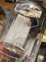
In the case of my recently acquired RevB, along with the 27v zener came a lovely vintage Tung-Sol 5881 with a hole already fried in the plate (see attached). And my recently acquired RevA is red-plating whatever tube I dare to put in V3.
So seeing a similar issue in both of the only 2 RD-50s I've ever seen the inside of, seems logical to look for a more proactive way to deal with it. Kinda why we're DIYers, right? Surely after 40 years of field-testing there's gotta be a couple of reliability-centered mods out there to consider?
In the end I just want these guys to play nice with my pricey glass bottles and maybe be able to start gigging and recording with them without making sure I can afford a new OPT and a set of NOS STRs first. I'd rather sacrifice a 50 cent component to protect a 50 dollar tube if there's a way to do it.
Or maybe it's not worth running NOS tubes in this kind of circuit at all? I actually have no idea at this moment if cascoded output tubes are capable of coloring the sound at all. I've tried figuring out where saturation would start to happen in this configuration using traditional load lines but it's not making any sense to me. But if these tubes stay pretty much linear right up to max dissipation, maybe it makes more sense to just run cheaper tubes and hope they don't take the OPT with them when they go?
And/or maybe I should invest my time on adding a Hi/Lo power option like my 75 and almost every other MM model?
In the case of my recently acquired RevB, along with the 27v zener came a lovely vintage Tung-Sol 5881 with a hole already fried in the plate (see attached
). And my recently acquired RevA is red-plating whatever tube I dare to put in V3.So seeing a similar issue in both of the only 2 RD-50s I've ever seen the inside of, seems logical to look for a more proactive way to deal with it. Kinda why we're DIYers, right? Surely after 40 years of field-testing there's gotta be a couple of reliability-centered mods out there to consider?
In the end I just want these guys to play nice with my pricey glass bottles and maybe be able to start gigging and recording with them without making sure I can afford a new OPT and a set of NOS STRs first. I'd rather sacrifice a 50 cent component to protect a 50 dollar tube if there's a way to do it.
Or maybe it's not worth running NOS tubes in this kind of circuit at all? I actually have no idea at this moment if cascoded output tubes are capable of coloring the sound at all. I've tried figuring out where saturation would start to happen in this configuration using traditional load lines but it's not making any sense to me. But if these tubes stay pretty much linear right up to max dissipation, maybe it makes more sense to just run cheaper tubes and hope they don't take the OPT with them when they go?
And/or maybe I should invest my time on adding a Hi/Lo power option like my 75 and almost every other MM model?
Attachments
> Peavey VTX
Ah. I had forgot those guys. And Jack signed-off on it. However I'm not going to re-visit that.
Guessing you're not a fan??

I had a pair of all-tube Peavey Encore 65s a few years back. Never got the sound I wanted out of them, but I didn't know what I was doing anyway - wasn't the car as much as the driver... What I really didn't like was having the sockets mounted on the PCBs. They were browning from heat and starting to warp so I had to let them go. 500v on the plates AND screens IIRC.
I think the later MMs will be fine with new Russian 6550s. The tube does what the transistor tells it to do. 6550 is largely a super-6L6. KT88 also but the bottle is taller.
The Peavey design makes my brain hurt. If it also has hot bottles on PCB, then I will be sure not to let any follow me home.
The Peavey design makes my brain hurt. If it also has hot bottles on PCB, then I will be sure not to let any follow me home.
- Home
- Live Sound
- Instruments and Amps
- Music Man RD-50s - Why So Many Output Section Issues?