Hi all, new around here. Conforming to the cliche I bought a cheap amp off ebay and surprise surprise it's got issues. It's an early H&H S130 Power Amp (light up version). The seller has changed the filter caps and said it was ok when he sent it but...when I power it up there's a loud 50/60 cycle hum (unaffected by volume control).
I've opened it up and nothing is obviously loose or damaged, took readings from the filter caps and one was zero from both poles and the other zero from positive and -50 from negative. I've had a look at the schematics floating around but they're slightly too blurred to be useful an an ignoramus such as myself unfortunately.
Can anyone offer some general help regarding how to trouble shoot the hum? Or perhaps some specific advice if you're familiar with the model?
I'm not expert with electronics but not a complete idiot either (depending who you ask...), quite ok with using a multimeter and safe tinkering (I know how to drain caps etc).
thanks in advance,
Nick
Last edited:
Hi Nick
First off all: do NOT, repeat NOT!!!, make any further work or tests with a speaker connected - it may very likely release the blue smoke that powers electronics.
I do not have the schematics available - but if I recall way back the H&H's I've seen are DC-coupled (no output capacitor, instead a double +/- power supply is used) - and the following is based on that assumption.
Having one of the filter capacitors with zero voltage across while another has 50V is a sign of either: Serious malfunction in the power supply (may be just a fuse), broken wire(s) to the capacitor, a power supply rail may be shorted to ground.
One good thing is this is an old pre-classD circuit, which allows for testing with much lower voltages than intended in the design.
First step would be to check the power supply.
I would do following:
Disconnect speaker
Connect a low power (20W) light-bulb in series with the AC-power cord (or use variac - which is likely not part of your tool box")
Check that the speaker is disconnected
Turn amplifier on (with light bulb in series)
If this lights up a short while, that is OK, but it should not produce more than a glow afterwards If it does you are probably going to hunt after a component, that has failed to a short.
Measure the voltages on the filter capacitors - still expected that one will have a voltage across and the other no voltage.
Follow the wiring from the capacitor with zero voltage to (expected) a diode bridge and measure the voltage here.
If there is a voltage here then the connection to the capacitor is broken somehow.
If no voltage then measure at the other side of the diodes (using the AC-voltage setting)
If the is voltage here - the diodes may be faulty.
Lets start here
Cheers
Martin
First off all: do NOT, repeat NOT!!!, make any further work or tests with a speaker connected - it may very likely release the blue smoke that powers electronics.
I do not have the schematics available - but if I recall way back the H&H's I've seen are DC-coupled (no output capacitor, instead a double +/- power supply is used) - and the following is based on that assumption.
Having one of the filter capacitors with zero voltage across while another has 50V is a sign of either: Serious malfunction in the power supply (may be just a fuse), broken wire(s) to the capacitor, a power supply rail may be shorted to ground.
One good thing is this is an old pre-classD circuit, which allows for testing with much lower voltages than intended in the design.
First step would be to check the power supply.
I would do following:
Disconnect speaker
Connect a low power (20W) light-bulb in series with the AC-power cord (or use variac - which is likely not part of your tool box
Check that the speaker is disconnected
Turn amplifier on (with light bulb in series)
If this lights up a short while, that is OK, but it should not produce more than a glow afterwards If it does you are probably going to hunt after a component, that has failed to a short.
Measure the voltages on the filter capacitors - still expected that one will have a voltage across and the other no voltage.
Follow the wiring from the capacitor with zero voltage to (expected) a diode bridge and measure the voltage here.
If there is a voltage here then the connection to the capacitor is broken somehow.
If no voltage then measure at the other side of the diodes (using the AC-voltage setting)
If the is voltage here - the diodes may be faulty.
Lets start here
Cheers
Martin
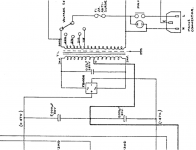
Just found the schematics:
http://i652.photobucket.com/albums/uu244/kvimbo/temp/HH_S130.jpg?t=1267365491
There are two 4 AMP fuses between the power supply and the amplifier.
Remove these - and then go hunting why one of the power rails are zero.
Cheers
Martin
http://i652.photobucket.com/albums/uu244/kvimbo/temp/HH_S130.jpg?t=1267365491
There are two 4 AMP fuses between the power supply and the amplifier.
Remove these - and then go hunting why one of the power rails are zero.
Cheers
Martin
Hi Nick
If the fuse was dead, that may have caused the hum as the amplifier then only have had half the supply, very possibly letting the ripple from the power supply getting through to the speaker.
If the fuse is one of these small 5x20 mm glass tubes with metal caps in both ends I have though seen them come apart just by handling.
But: this does not explain that you measured zero volts across one of the filter capacitors.
So before doing anything else, keep the fuses out, disconnect the speaker (did I remember to tell you that?) and then measure the voltage on the filter capacitors - if the power supply is working, you should measure + and - 50V compared to ground.
If this works, switch off and discharge the capacitors (gently with a resistor), then replace working fuses and switch amplifier on again - using the light bulb trick.
Measure voltages again - if one is zero (ish) you may have a short in the amplifier itself.
But time for testing the power supply
Cheers
Martin
If the fuse was dead, that may have caused the hum as the amplifier then only have had half the supply, very possibly letting the ripple from the power supply getting through to the speaker.
If the fuse is one of these small 5x20 mm glass tubes with metal caps in both ends I have though seen them come apart just by handling.
But: this does not explain that you measured zero volts across one of the filter capacitors.
So before doing anything else, keep the fuses out, disconnect the speaker (did I remember to tell you that?
) and then measure the voltage on the filter capacitors - if the power supply is working, you should measure + and - 50V compared to ground.If this works, switch off and discharge the capacitors (gently with a resistor), then replace working fuses and switch amplifier on again - using the light bulb trick.
Measure voltages again - if one is zero (ish) you may have a short in the amplifier itself.
But time for testing the power supply
Cheers
Martin
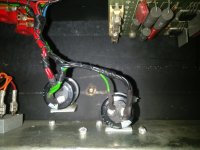
Hi Martin - Thanks, I'm going to try that tonight! Before I do, something has been troubling me in terms of the wiring for the caps. It's very neat but looks like it's in series (assuming green is ground).
I'm not good at reading schematics but they look like they should be parallel?
I'm not good at reading schematics but they look like they should be parallel?
Attachments
Hi Martin - Thanks, I'm going to try that tonight! Before I do, something has been troubling me in terms of the wiring for the caps. It's very neat but looks like it's in series (assuming green is ground).
I'm not good at reading schematics but they look like they should be parallel?
Just to avoid any doubt: The schematics are very clear that the filter capacitors are coupled in series with the (green) connection between the two capacitors being connected to ground.
The picture you have uploaded matches this - likely with the red wires being at +47V and the black being -47V (the colours assuming slightly normal practice).
Note that the schematics says 47V where you measure 50V - this difference is of no consequence.
Cheers
Martin
Hi Martin,
Some success and some failure - I followed your instructions and both caps now measure correctly. I've replaced the fuses and the caps are still measuring as expected.
The hum is gone...however, now I'm not getting *any* output from the amp. I'm going to clean the fuse mounts as they're not in great condition (some kind of white residue?). What would be the next de-bugging step you'd suggest?
million thanks,
Nick
"Hum is gone"
You naughty you - you have connected the speaker!
I can only recommend that you disconnect the speaker and keep it disconnected until you are confident that the amplifier is operational.
The total lack of sound may be an indicator of you have burned the speaker letting out the blue smoke that makes all electronics work.
Step 1: If the voltages on the power supply is OK then measure the DC on the output.
With a working amplifier this should be close to zero - well, less than 1V.
Step 2: if the DC is OK as described above, apply an input signal, while using the AC range on your multimeter and measure if something gets out.
I can not give you a complete process for analysis here - whole books has been written on this subject, so lets take a small step at a time
BUT KEEP THE SPEAKER DISCONNECTED, please
PS: you may want to check that the speaker is still OK - on an other, working amplifier.
Hi Nick
Good - I just don't want you to loose the speaker
While you are at it:
Step 3: Measure the voltage across the base-emitter on the output transistors.
Those are mounted either on the backside of the case or on a separate heatsink.
The base and the emitter are the two leads sticking out through holes in the heatsink (or back plate).
These transistors (labelled Q1 and Q2 in the schematic) are housed in a TO-3 case. To know what you are looking for look at:
TO-3 - Wikipedia
Edit: If you look at the photo you uploaded of the internals of the amplifier, there are two sets of connections labelled "E", "B" and "C" (these are also visible in the schematics). The base-emitter measurement can be made on these connections ("E" - emitter and "B" - base).
You should measure around 0.6V on each transistor.
Warning: Be careful when measuring on parts in the amplifier.
Even if you have the light bulb in series with the power supply (you did remember to do this, right?) there will be plenty of charge and nice sparks in the filter capacitors to destroy any of the transistors if you make the wrong short with the measuring tips.
Cheers,
Martin
Last edited:
Hi Martin,
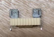
Sorry for the slow reply - work got in the way of tinkering! There was no AC reading at the output but having replaced the 4A fuses, I was suspicious of the fuse holders - they looked rather corroded. I probed them and they weren't passing current across. I ordered some new fuse holders and replaced the old ones (fuzzy picture attached) and hey-presto...it works! AC reading at output and plugged into the speaker it's sounding good!
Problem solved - many many thanks for your help.
Nick
Attachments
- Home
- Live Sound
- Instruments and Amps
- Troubleshooting 50/60 cycle hum on an HH S130