I'm basing this on a 5e3 Fender Deluxe schematic, but making some significant changes. (It will not sound like a miniature Fender Deluxe).
What I've determined so far.
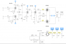
Hammond 269AX PT - 250V C.T. @ 115mA, 6.3V @ 2A (I want to push the voltage, I've seen lots of homebrew amps with Russian subminiatures used at lower voltages but I want to see what they can do pushing the limits.)
full bridge diode rectifier IN4007's - This is one of the changes that will make it sound less like a Fender Deluxe, but there is no subminiature rectifier tube that I'm aware of that will work and my transformer has no 5V winding. This SS rectifier will work fine.
Hammond 1750E output transformer - 8,500 C.T. primary, 8 ohm secondary for push-pull operation. (I did a lot of research and head-scratching on this one. I can't find a load resistance spec for 6p30b tube. I saw many builds with varying output transformers, most lower voltage, some SE. Eventually I found a "rule of thumb" formula that came out to around 4600 ohm per tube, so I think this 8,500 ohm primary will work okay. If I'm wrong about this, let me know.
6p30b power tubes in push-pull. Though small these tubes are rated @ 250V with 350V at cutoff, and flow 35+mA, so IMO they are about 1/2 the power of 6V6's and I intend to get all I can out of them.
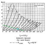
6n17b in V1 and V2. At 75mu these dual triodes are about the closest thing to a 12ax7. The curves are a bit different, but follow the same general shape. Some of the capacitances are the same, so I'm hoping the Miller capacitance is also similar.
Mounting the tubes - I'm custom building an eyelet board, so I could put a row of eyelets and solder the leads directly to the board and have them stick through holes in the top of the chassis, but what I'm also considering is putting color coded shrink wrap on the leads. Then, on the ends of the leads, taking pieces of hypodermic needle stock and soldering the leads through it so they'll fit into a standard 9-pin miniature socket.
That's about all I got for now, please offer criticisms, suggestions, etc.... I will crunch the numbers and come up with values for the resistors and capacitors and my next post will have a schematic with all that.
What I've determined so far.
Hammond 269AX PT - 250V C.T. @ 115mA, 6.3V @ 2A (I want to push the voltage, I've seen lots of homebrew amps with Russian subminiatures used at lower voltages but I want to see what they can do pushing the limits.)
full bridge diode rectifier IN4007's - This is one of the changes that will make it sound less like a Fender Deluxe, but there is no subminiature rectifier tube that I'm aware of that will work and my transformer has no 5V winding. This SS rectifier will work fine.
Hammond 1750E output transformer - 8,500 C.T. primary, 8 ohm secondary for push-pull operation. (I did a lot of research and head-scratching on this one. I can't find a load resistance spec for 6p30b tube. I saw many builds with varying output transformers, most lower voltage, some SE. Eventually I found a "rule of thumb" formula that came out to around 4600 ohm per tube, so I think this 8,500 ohm primary will work okay. If I'm wrong about this, let me know.
6p30b power tubes in push-pull. Though small these tubes are rated @ 250V with 350V at cutoff, and flow 35+mA, so IMO they are about 1/2 the power of 6V6's and I intend to get all I can out of them.
6n17b in V1 and V2. At 75mu these dual triodes are about the closest thing to a 12ax7. The curves are a bit different, but follow the same general shape. Some of the capacitances are the same, so I'm hoping the Miller capacitance is also similar.
Mounting the tubes - I'm custom building an eyelet board, so I could put a row of eyelets and solder the leads directly to the board and have them stick through holes in the top of the chassis, but what I'm also considering is putting color coded shrink wrap on the leads. Then, on the ends of the leads, taking pieces of hypodermic needle stock and soldering the leads through it so they'll fit into a standard 9-pin miniature socket.
That's about all I got for now, please offer criticisms, suggestions, etc.... I will crunch the numbers and come up with values for the resistors and capacitors and my next post will have a schematic with all that.
 Moved to Instruments & Amps
I'm basing this on a 5e3 Fender Deluxe schematic, but ... ... ....
Kuehnel's latest book analyzes most of Fender's DeLuxes, topology, gain, and operating points. I learned some about Leo's thinking (more about fashion in the g-amp racket 1950s-1960s). May be worth a look.
Guitar Amplifier Electronics: Fender Deluxe by Richard Kuehnel
Well actually 6N21B is far closer to a 12ax7 in terms of mu, rather than the 6N17B, which is a wimpy halfway house affair, somewhere between a 12AT, AU7, and 12AX7.
Regarding 6P30B-R, they can operate at 350V Vao, in cutoff.
I run then at 320V B+, and 15mA current. This is very close to their dissipation. Probably 0.9W single ended 3W PP.
Regarding 6P30B-R, they can operate at 350V Vao, in cutoff.
I run then at 320V B+, and 15mA current. This is very close to their dissipation. Probably 0.9W single ended 3W PP.
Last edited:
Well actually 6N21B is far closer to a 12ax7 in terms of mu
True, the 6n21b would be a good choice except I have a box of 50 6n17b NOS.
Glad to hear you run 6p30b @ 320V, 15ma. I'm looking to be in that range, I came up with 300V, 20ma. We'll see if it works out. I may have to put a dropping resistor after the rectifier.
I would not be too crazy about the needle thing, not how well the solder will take to the stainless steel. You could take an old 9-pin tube and break it and use the bottom of it. Pot atound the glass with epoxy. Could also make a nifty wire cage or some kind of shield over it if you are a creative type.Some have used a 0.1" pin header although I would go a double spacing around the high voltage on the anode just in case.
You could take an old 9-pin tube and break it and use the bottom of it. Pot atound the glass with epoxy.
I will try that, thanks!
....Not sure if I'd be better off to try to crunch the numbers on the power supply resistors, or put it together and change them as needed.
20k-20k-20k does not look like ANY tube amp I ever met.
Since that power stage may suck near 100mA, that first resistor drops 200 Volts (or more, since this is pulse power).
Just as a general thought, I would be thinking 200-2k-20k... a progression from high level high power to low level low power.
Or *STEAL* values from the known-good DeLuxe. (zero, 5k, 22k)
https://robrobinette.com/images/Guitar/5E3P_Build/5E3_Schematic_Annotated.gif
The Russian tubes do not use different electrons.
The Russian tubes do not use different electrons.
haha! that is a true statement! Sounds like I better get out the calculator and figure it out. I need "A" to be 300V, B and C have some leeway.
dropping resistors in filter
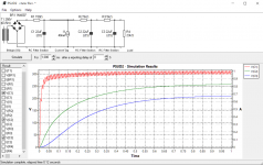
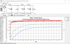
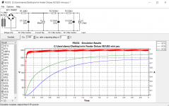
I used PSU Designer II calculate the values of dropping resistors on the power supply filter. If I have all the values correct, a 150 ohm, 5Kohm, and 5Kohm will put me about A- 300V, B-260V, and C- 215V.
(The 40mA load is to represent the output transformer and 6p30b's in push-pull at idle. The 23Kohm load represents the preamp section.) The transformer specs wanted me to enter a resistance, which I had no clue about, so I left it at 63.5 ohms. I hope this value is close or doesn't throw the rest of my numbers out of whack too badly!
Attachments


...The 40mA load is to represent the output transformer and 6p30b's in push-pull at idle....
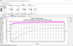
At full power, a 8KCT load @ 300V will suck more like 70mA. How much does that change things?
At full power, a 8KCT load @ 300V will suck more like 70mA. How much does that change things?
FYI- my output transformer Hammond 1750E is 8,500 ohm CT pri. / 8 ohm sec.
According to PSU Designer II, 70 mA current in the power amp section drops voltages approx. 20V. Attached images, 1rst shows 40 mA, 2nd shows 70 mA.
Attachments
Last edited:
If you right click on the 23k resistor (or any load) you can change it to a current sink, most preamp tubes guesstimated at 1 mA. The screen and output stage you can also righ click and change the values as well as select stepped response, where you can put in the Class B current values. You have to specify the time for the step response, may need to adjust the total time longer also.
If you right click on the 23k resistor (or any load) you can change it to a current sink, most preamp tubes guesstimated at 1 mA.
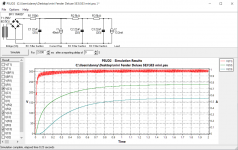
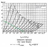
That's interesting, the 6n17b has an anode current of 3.3mA * 4 = 13.2mA. That value keeps A-300V, but drops B-235V, C-170V. If I instead choose 9.9mA the graph matched my original graph for 23Kohm resistance.
I thought I calculated the 23Kohm resistance very carefully, but something doesn't agree here. Is it possible that the phase inverter section doesn't count? Or some other reason why it would be 3 preamp currents instead of 4?
Attachments
Last edited:
That's interesting, the 6n17b has an anode current of 3.3mA * 4 = 13.2mA. ...
The number on the datasheet is NOT your number, but a show-off spec, often for power-crazed uses like RF stages.
You have one section with a 150k plate resistor. To make 3.3mA flow in that you would need 490V plus tube losses, so like 550V total. Instead it is very likely to run near 210V/2= 105V across 150k or 0.7mA. (Actually lower.) And similar <3.3mA values for the other sections.
Attachments
Last edited:
You have one section with a 150k plate resistor. To make 3.3mA flow in that you would need 490V plus tube losses, so like 550V total. Instead it is very likely to run near 210V/2= 105V across 150k or 0.7mA. (Actually lower.) And similar <3.3mA values for the other sections.
That particular section is based on Rob Robinette's lead channel mod for 5E3. (It should have a 0.0047uF coupling cap btw) Wouldn't his section operate similarly? (see attached 12AY7 load line).
I'm still not sure what the problem is, if I enter these low current values <4mA into PSU Designer, there will be virtually no voltage drop between A, B, and C! They will all be up around 300V!! That can't be right. Should I forget that and go with what it gave me when I figured it for 23Kohm load?
Attachments
Last edited:
power supply w/ 4.6mA load
Okay, I think I finally figured this out.
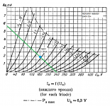
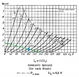
I decided to run preamp tubes @240V. I constructed load lines for 42k, 75k, and 150k plate resistors w/ bias point @160V. That gave me 1.8mA, 1.1mA(*2), and 0.6mA for a total of 4.6mA.
I plugged 4.6mA into PSU Designer II and fiddled with the resistor values until I got A-300V, B-270V, C-240V. It came out to 220, 6.5K, 6.5K.
Okay, I think I finally figured this out.
I decided to run preamp tubes @240V. I constructed load lines for 42k, 75k, and 150k plate resistors w/ bias point @160V. That gave me 1.8mA, 1.1mA(*2), and 0.6mA for a total of 4.6mA.
I plugged 4.6mA into PSU Designer II and fiddled with the resistor values until I got A-300V, B-270V, C-240V. It came out to 220, 6.5K, 6.5K.
Attachments
bias point
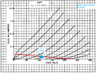
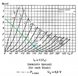
I changed my mind about biasing @160V. My cutoff point is 240V/0mA and lies on the -4V grid curve. I want the output to be able to swing between 0V and -4V so moved the bias point to where the -2V grid curve crosses the load line.
This changed my currents to 1mA, 0.7mA, 0.5mA depending on plate resistor (42K, 75K, 150K). Now my total current is 2.9mA rather than 4.6mA.
I plugged 2.9mA into PSU Designer II and fiddled with the resistor values until I got A-300, B-270, C-240 again. It came out to 220, 10.5K, 10K
Then I used the grid voltage and anode current to re-calculate the cathode bias resistors in the preamp.
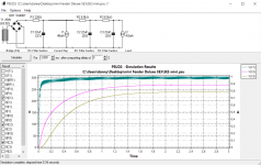
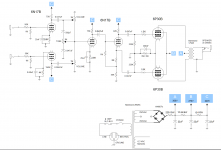
attached are the new (and hopefully correct load lines and PSU Designer simulation). I also attached the schematic-in-progress with updated cathode bias resistors and power supply specs.
I changed my mind about biasing @160V. My cutoff point is 240V/0mA and lies on the -4V grid curve. I want the output to be able to swing between 0V and -4V so moved the bias point to where the -2V grid curve crosses the load line.
This changed my currents to 1mA, 0.7mA, 0.5mA depending on plate resistor (42K, 75K, 150K). Now my total current is 2.9mA rather than 4.6mA.
I plugged 2.9mA into PSU Designer II and fiddled with the resistor values until I got A-300, B-270, C-240 again. It came out to 220, 10.5K, 10K
Then I used the grid voltage and anode current to re-calculate the cathode bias resistors in the preamp.
attached are the new (and hopefully correct load lines and PSU Designer simulation). I also attached the schematic-in-progress with updated cathode bias resistors and power supply specs.
Attachments

....if I enter these low current values <4mA into PSU Designer, there will be virtually no voltage drop ....
Ohms Law is a friend.
Yes changing the preamp feed changes the load on the first filter but the effect is swamped by the much larger current in the power stage. And this is NOT brain surgery. 25V one way or another makes about no difference at the end of the night.
...It came out to 220, 10.5K, 10K .. attached are the new (and hopefully correct load lines and PSU Designer simulation).
Certainly 10.5k can be 10k. However have you allowed for the power tubes' screen current? Did any Fender Deluxe run as much as 10k in the combined screen/preamp feed?
- Home
- Live Sound
- Instruments and Amps
- russian subminiature 6n17b 6p30b P2P scratch build