Hi does anyone have a schematic for a vortexion fet 50/70 or know where I can purchase a copy?
I've looked everywhere not been able to find one. I know Vortexion amp schematics are pretty scarce except the 100 watt ef86 version. If I'm in the wrong thread point me in the right direction.
I've looked everywhere not been able to find one. I know Vortexion amp schematics are pretty scarce except the 100 watt ef86 version. If I'm in the wrong thread point me in the right direction.
I was wondering if I could although this being a rare model convert it from a 100v line output to a 4r - 8r output by removing the transformers and installing a single toroidal transformer?
Seems like an interesting project plus I now have a schematic so know what I have in terms of circurity.
Has anyone done this before?
Any thoughts most welcome.
Seems like an interesting project plus I now have a schematic so know what I have in terms of circurity.
Has anyone done this before?
Any thoughts most welcome.
...I now have a schematic so know what I have in terms of circurity....
And we don't.
Suggest you upload it here if you want any answers.I now have a schematic so know what I have in terms of circurity
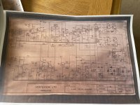
Not a great schematic but better than nothing. Looking at it the op looks like it can be re wired to 5/15 ohm setting to right on left is the 100v balanced setting. Could be wrong pic attached.
So any thoughts gone very quite!
Attachments
So any thoughts gone very quite!
Not even a day gone by. Hey, it may seem like we live on here but it was the weekend and life is full of other pursuits when the weather is nice.
Put a sine wave in and measure the voltage off the transformer primary and secondary. My thought is you might be able to take an output off the primary test points/terminals. But others may see something I am missing.
Yeah you can say that again. Everyone has gone mad I live by the coast and the amount of people sitting on top of each other is crazy. All I can say it will be an interesting winter for sure. If you can't see it coming stay well clear is my moto.
Back to this one yes thats worth a look. I'm sure you can. Looking at schematic aswell looks to be not so much a swith but bit like a quad mono block just move the wiring taps around for different output rating. I can do it on my trio stereophonic but thats got a proper switch. Actually thinking about it thats a possibility incorporate a switch terminal plenty of room in there for that. Just thinking out aloud.
Thanks for info I'll give that a go tomorrow not used me scope for ages.
I'd strongly suggest you use a 'line transformer' to interface the '100V' line to your speaker - that is what the amp was designed to do.
Any hope that you could modify that amp would mean you would have to reverse engineer it in detail for starters, and then re-design it using parts that are not yet defined or possibly available. For starters imho you should go through and restore the amp and technically describe what all the circuitry does and confirm correct intended operation.
Any hope that you could modify that amp would mean you would have to reverse engineer it in detail for starters, and then re-design it using parts that are not yet defined or possibly available. For starters imho you should go through and restore the amp and technically describe what all the circuitry does and confirm correct intended operation.
The schematic he found clearly shows low-Z just connected to raw amplifier output, at transformer primary (which makes it redundant).
However I do not see that switch in pictures and suspect it is not in his amp.
And this amp is a museum piece. I'll be surprised if is isn't half-dead, ready to put 40 Volts steady DC across his speaker. In 1976 I was repairing similar amps monthly (in hard service). Amplifier design did improve a LOT in the next 20 years. Bigger better amplifiers are readily available used.
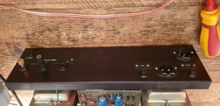
The OP hasn't shown a photo of the rear panel, but describes a 100V line output, which is not on the schematic, so there is obviously a concern as to what he has got. The output stage looks to have a 2N3054 driver but I can't make out the main npn, which must be something like a 2N3055 to allow 70W output from +/-50V rails.
There are lots of transistor output stage PA amps (eg. TOA) getting tossed out - many of them have that form of line transformer (low ohms to various speaker impedances). The output transformer in the amp may even have unused and tucked away taps that correspond to speaker level. The OP just has to do his homework.
There are lots of transistor output stage PA amps (eg. TOA) getting tossed out - many of them have that form of line transformer (low ohms to various speaker impedances). The output transformer in the amp may even have unused and tucked away taps that correspond to speaker level. The OP just has to do his homework.
I haven’t started on this yet but just looking to get some feedback which is great.
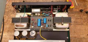
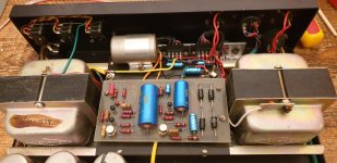
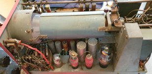
Yes it’s a museum piece for sure that’s why I got it rare as hens teeth. It’s definitely not dead for sure already had it fired up but the Philips caps and psu caps need replacing. Pic of back.
Oops ignore second pic it’s a scope off a battle ship WWII.
Yes it’s a museum piece for sure that’s why I got it rare as hens teeth. It’s definitely not dead for sure already had it fired up but the Philips caps and psu caps need replacing. Pic of back.
Oops ignore second pic it’s a scope off a battle ship WWII.
Attachments
The OP ..... describes a 100V line output, which is not on the schematic, so there is obviously a concern as to what he has got..... ....something like a 2N3055 to allow 70W....
Are we not looking at the same schematic? The 100V output is clearly marked, so is a 5/15 output. One is from a CT winding. The other is DC coupled between the amplifier center-point and the power supply center-point.
The output devices are an RCA-specific sortout of 2N3055 selected for 95V Vcer. Original to-spec 2N3055 will not survive these voltages (many did, because many were better than spec; all the fat-base '3055s are gone now and the planars are wimps).
https://cdn.datasheetspdf.com/pdf-down/4/0/6/40611-RCA.pdf
Attachments
- Home
- Live Sound
- Instruments and Amps
- Vortexion Fet 50/70