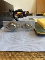
Well pulled apart interesting set up differs from schematic. The only transistors are BC114 K30 2N3055 & 2N3054 paired on two separate heatsinks. Connection wise nicely done just plug.
Output at present is 5r.
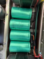
PSU 4 2500uf 50v was gonna try and reform them but since there so old leakage probably be too high it’s been in storage since 1983.
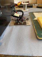
Anyhow I think 3 cans front end are mic transformers and the one on the psu board possibly a step down transformer possibly!
Anyhow some pics to follow see what you think.
Output at present is 5r.
PSU 4 2500uf 50v was gonna try and reform them but since there so old leakage probably be too high it’s been in storage since 1983.
Anyhow I think 3 cans front end are mic transformers and the one on the psu board possibly a step down transformer possibly!
Anyhow some pics to follow see what you think.
To me the 50/70W and the 5/15 ohm ratings ...... ....... 40636 devices.
The 30/50 model says 50W speech/music, 30W continuous sine. Reasonable for the day. So this model is 50W steady and 70W peaks?
The 5/15 is quite vague, true (even if 4/15). About 10 Ohms makes the power work out.
The 2N3055s found in this one may be later repairs or may be Vortexion selected to the 40646 specs. We did a lot of that cheating back in the day.
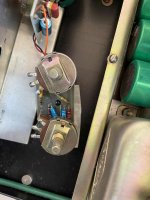
They look like they’ve been in there from day one. None of bolts or red paint removed off solder joints. Odd no grease just mica spacers? Think bc109 and bc 107 have been replaced with bc114. Couple of holes in psu board looks like components may have been in there only around 4 holes all other holes clean. The rest is all original from what I can see.
Psu caps replacing them with 3300uf caps bit higher but not really gonna make any difference sonically originals 2500uf. Not that we would hear. Then I’ll pull the others out and replace plus those tropical so called fish caps shame not swam off. Find outer casing goes dry and brittle on them. The rest seems fine I’ll check resistors see if any have drifted.
The op has total of 6 lead outs so me thinks you can change it round. Fairly easy to work on. So some subtle differences. Are you saying the parts you think may have been substituted are crap ones? Was not quite sure what ya meant.
I’ll try some pics again tomorrow rather frustrating today maybe there too big most over 7mb.
The 5/15 may be the acceptable speaker loading impedance range.
If you can test the turns ratio of the OPT and assume say 100V on secondary equates to a 46Vpk primary voltage swing (so 32.5Vrms) then a 15 ohm primary winding equates to a 142 ohm secondary. Similarly 70W and 100V give a secondary nominal impedance of 142ohm. It's also likely that the feedback winding aligns with some plausible turns ratio voltage like 2V.
If you can test the turns ratio of the OPT and assume say 100V on secondary equates to a 46Vpk primary voltage swing (so 32.5Vrms) then a 15 ohm primary winding equates to a 142 ohm secondary. Similarly 70W and 100V give a secondary nominal impedance of 142ohm. It's also likely that the feedback winding aligns with some plausible turns ratio voltage like 2V.
The schematic clearly shows that information to connect a speaker as you needed.
Only thing is you have to verify the schematic and actual model is the same.
The amp is a single supply design and the transformer is connected to the output transistors middle point to the middle point of the two capacitors of the power supply.
If the drawing is correct, you can connect the speaker to the same points. Do not disconnect the transformer, a feedback network is still connected.
The speaker and transformer will operate in parallel. Do not use the 100 v outputs.
The other solution is to use a 100 volt to 8 ohm line transformer.
Regards.
Just connect 5-15 ohm speaker to points shown at the schematic, as said above switched or not, and use as-is.
Why 5-15? .... well, it´s British!
Snd do NOT load it with a 4 ohm speaker, 5 ohm rating means you could use *three* 15 ohm speakers in parallel.
Personally I would not go below 8 ohm, go figure.
I faintly remember this ad or a very similar one, and it reeks of 60´s 70´s British Electronics mags, which I devoured at he time.
It would also be featured in the Wilmslow Audio page ad.
Last edited:
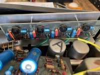
Definitely some was usd in the 70´s BUT:Anyone know why no heatsink compound used just mica washers? Not seen that before.
we are used to mineral loaded (typically zinc oxide) transfer paste but there is also a transparent non mineral version, Dow Corning makes a few, here we call them "silicone vaseline"
It works well, but maybe in 40 years plus quite a few heat cycles it may melt and slip away.
Personally I´d remove power transistors, wipe them clean, and remount with fresh mica and grease.

Just connect 5-15 ohm speaker to points shown at the schematic, as said above switched or not, and use as-is.
So there are two more blue and brown wires from op going to psu board so you could put some veto pins in there and tap from there. Terminate the two 100v wires and connect from psu board. So I’m bypassing them. Just a thought as there gonna be redundant. Not connected to a load. Think in one of pics you will see the brown and blue wires going to main board about 24awg. See attached pic.
Attachments
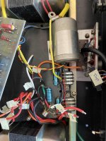
Well that’s interesting those two leads are giving me 3.5ohms.
Those Philips caps all gone way out. Difficult to read small ones can’t make my mind up if there 6.4v or 64v. There on tone board so can’t see them being high voltages. But higher is not gonna do any harm. If I put 6.4 and there 64 then asking for trouble. Those tropicals are actually in pretty good condition so gonna leave them in for now. If drifted soon find out when fired up.
Story so far.
So order cap time.
- Home
- Live Sound
- Instruments and Amps
- Vortexion Fet 50/70