Hi,
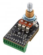
I just got my hands on a onboard seymour duncan BMP-1 preamp. It's a rev. 04. It was supposed to be the same kind of preamp as the ones coming inside Blackouts pickups, so i got interested.
Seymour duncan promote his preamp using another technic of imbalance compared to EMG differential amplifier with their simple input resistor difference in front of a lm4250.
I found a russian shematic of the blackout preamp on the web. I wasn't sure how good/true it was, but comparing to the BMP-1 preamp pcb, it seems really near, for most of it even for resistor values.
Since it's smd, i cannot get ceramic caps values.
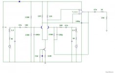
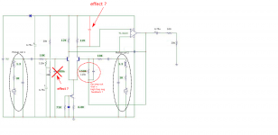
Picture 1 is russian forum's blackout schematic. Picture 2 is with the values and small changes i found on the BMP-1 preamp pcb (one way). Picture 3 is a web photo of the BMP-1.
This seems to be kind a current source differential amplifier + op amp, but i'm not good enough to say more. Really complicate stuff for what it is, so there must be something about imbalance input stuff that explain this choose.
On schematic, there's 3 stuffs i'm not sure about.
1. The "feedback" from op amp output to right fet input. 115k seems high, so it probably a Vref, but there's a cap too. Can't it act as low pass effect injecting negative feedback high frequencies on right input ? Or it is positive feedkback ? or none of that...? This way of referencing op amp output seems me really weird, i would have expected a referencing to a resistors virtual ground...
2.The 680p cap i crossed from the russian shematic, on the left fet seems really high. It's not on the BMP-1. It seems me a error. What do you think about it ?
3.The added capacitor in parrallel with the 12k resistor. Can it be a high pass, or a low pass ?
I'd like to tweak this little onboard preamp. I'll first change op amp for opa1692, bypass output cap with a nichicon muse, and add cap between op amp legs v+/v-.
But it should be interesting to see the effect on preamp response changing stuff around those 3 points (1. adding back a cap, 2 removing this cap, 3 changing cap value). Smd soldering isn't a problem at all.
Any suggestion of tweak ?
")
Thanks,
Best regards,
Damien
I just got my hands on a onboard seymour duncan BMP-1 preamp. It's a rev. 04. It was supposed to be the same kind of preamp as the ones coming inside Blackouts pickups, so i got interested.
Seymour duncan promote his preamp using another technic of imbalance compared to EMG differential amplifier with their simple input resistor difference in front of a lm4250.
I found a russian shematic of the blackout preamp on the web. I wasn't sure how good/true it was, but comparing to the BMP-1 preamp pcb, it seems really near, for most of it even for resistor values.
Since it's smd, i cannot get ceramic caps values.
Picture 1 is russian forum's blackout schematic. Picture 2 is with the values and small changes i found on the BMP-1 preamp pcb (one way). Picture 3 is a web photo of the BMP-1.
This seems to be kind a current source differential amplifier + op amp, but i'm not good enough to say more. Really complicate stuff for what it is, so there must be something about imbalance input stuff that explain this choose.
On schematic, there's 3 stuffs i'm not sure about.
1. The "feedback" from op amp output to right fet input. 115k seems high, so it probably a Vref, but there's a cap too. Can't it act as low pass effect injecting negative feedback high frequencies on right input ? Or it is positive feedkback ? or none of that...? This way of referencing op amp output seems me really weird, i would have expected a referencing to a resistors virtual ground...
2.The 680p cap i crossed from the russian shematic, on the left fet seems really high. It's not on the BMP-1. It seems me a error. What do you think about it ?
3.The added capacitor in parrallel with the 12k resistor. Can it be a high pass, or a low pass ?
I'd like to tweak this little onboard preamp. I'll first change op amp for opa1692, bypass output cap with a nichicon muse, and add cap between op amp legs v+/v-.
But it should be interesting to see the effect on preamp response changing stuff around those 3 points (1. adding back a cap, 2 removing this cap, 3 changing cap value). Smd soldering isn't a problem at all.
Any suggestion of tweak ?
Thanks,
Best regards,
Damien
Attachments
Last edited:
I just get on something...I didn't looked that much at first at how coil where differently loard on the 2 shematic. But looking on thread about emg 81 preamp variant, it appear me that on the first schematic i posted, coil is loaded with 150k/150k=75k on the left side, whereas on right input with only 150k. Coil resonnance should be lower in frequency and more damped for the coil on left input. That is how seymour deals with coil imbalance. It wouldn't have worked with op amp differential amp since it would have affected gain and so CMRR. That it what justify such a typology.
If so, on the bmp-1, if i want the same character as blackouts, i can deal with the 115k resistor going between the two 20k resistor, for example replacing it with 50k + 500k trimer.
May i be right ?????
If so, on the bmp-1, if i want the same character as blackouts, i can deal with the 115k resistor going between the two 20k resistor, for example replacing it with 50k + 500k trimer.
May i be right ?????
- Status
- This old topic is closed. If you want to reopen this topic, contact a moderator using the "Report Post" button.