Greetings,
I am new to this site and DIY electronics in general so please be gentle.
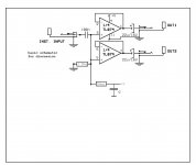
I need to split the input from an electric instrument into 2 outputs to effectively send down 2 effects channels and finally to 2 separate amplifiers. I found a schematic (attached) which I think does what I want to do. However, I only have 5v to play with and the TL074 seems to require 6 minimum and I suspect that is +/-6.
All I have to work with is +5v, Ground, and the instrument input. I think I know how to create +/-2.5 from the 5v.
So my questions are:
Thank you for any assistance.
I am new to this site and DIY electronics in general so please be gentle.
I need to split the input from an electric instrument into 2 outputs to effectively send down 2 effects channels and finally to 2 separate amplifiers. I found a schematic (attached) which I think does what I want to do. However, I only have 5v to play with and the TL074 seems to require 6 minimum and I suspect that is +/-6.
All I have to work with is +5v, Ground, and the instrument input. I think I know how to create +/-2.5 from the 5v.
So my questions are:
- Is there a good op amp that will operate at +/- 2.5?
- If I remove the "Loop Through" from the schematic, replace the TC074 with something that runs +/-2.5v will this work?
- Am I correct in assuming that if I put +5 on the v+ and ground on the v- I am effectively getting +/-2.5?
Thank you for any assistance.
Attachments
This is a component that fronts a 5v system in a portable platform. That system is running of a 5v battery pack as would be used by a mobile phone for extra power.
The portable platform is Raspberry Pi based so 5v, though there is 3.3v easily accessible.
So i am looking for a simple splitter. I have been told that I could just use a Y-Splitter but I also read that can have a significant effect on the quality of the sound on one or both legs of the split. Hence the desire for an electronic solution.
Claude
I want to think about this device as a "pedal" so any instrument could be plugged into it. I assume this means that a small preamp would have to be placed between the passive instrument and the pedal to make it appear the same as an active instrument. So let's assume active.
And either magnetic, or pizeo pickups.
Is there a solution?
And either magnetic, or pizeo pickups.
Is there a solution?
@leadbelly
My goal is to build a bit of kit for myself and several musician friends.
No, I don't know anything about electronics other than a bit covered in college physics many years ago, and what I have read in the past couple of months. But then, I thought I basically said that at the beginning.
I am a software engineer who has been playing with Raspberry Pi and learning what I can. So perhaps this project is a bit of a stretch for me, but I'm still looking at how to do it and to understand how to do the calculations.
So as I said, I have 5v (or 3.3v) and ground as that is what the pi runs on/provides. And I want to build a signal splitter for musical instruments. I have seen a number of schematics for various examples and I think I am beginning to understand how they work.
So if anyone can point me to how to build a signal splitter when I only have +v and ground, and an article or youtube video that explains how to do the calculations (an perhaps a bit of why) I would greatly appreciate it.
You said to assume active, that there would be a pedal in between the instrument and the splitter. If so a passive Y splitter will do the job.
If you insist on making an active splitter and need it to accept pedal outputs, 5V simply will not do the job. You can buy a DC-DC boost converter on Ebay or Aliexpress to give you a higher voltage to work with.
If you insist on making an active splitter and need it to accept pedal outputs, 5V simply will not do the job. You can buy a DC-DC boost converter on Ebay or Aliexpress to give you a higher voltage to work with.
Almost there.
TL074 will NOT work freom single +5V supply.
Old school solutions which I have personally used (being an .... ahem! .... "old" school guy") myself ) :
myself ) :
1) much despised by audiophiles LM358 will work perfectly well in the circuit above, being DESIGNED for single +5V supply operation.
Admittedly expecting some data or instrumentation to be fed to 5V powered digital stuff, but *does* work with Audio and unity gain buffer is the easiest application., it will do.
That said, search for a modern equivalent, ask Mr Google
2) make 2 single transistor emitter followers.
Bias: single 1M resistor from base to +5V for both.
Collectors to +5V
Emitters to ground through 4k7 resistors, audio out from each through 1uF electrolytics.
Use BC547C or similar.
Don´t make me draw the schematic
TL074 will NOT work freom single +5V supply.
Old school solutions which I have personally used (being an .... ahem! .... "old" school guy
myself ) :1) much despised by audiophiles LM358 will work perfectly well in the circuit above, being DESIGNED for single +5V supply operation.
Admittedly expecting some data or instrumentation to be fed to 5V powered digital stuff, but *does* work with Audio and unity gain buffer is the easiest application., it will do.
That said, search for a modern equivalent, ask Mr Google
2) make 2 single transistor emitter followers.
Bias: single 1M resistor from base to +5V for both.
Collectors to +5V
Emitters to ground through 4k7 resistors, audio out from each through 1uF electrolytics.
Use BC547C or similar.
Don´t make me draw the schematic
- Status
- This old topic is closed. If you want to reopen this topic, contact a moderator using the "Report Post" button.
- Home
- Live Sound
- Instruments and Amps
- 5v signal splitter for elec guitar (or other instrument)