First of all - a kind and big Hello! to everyone! ")
I hope I found myself in the right place to talk about such ideas and obviously to ask questions in the search of answers and solutions. I'm happy to have found this forum.
I'm in my 20's doing some electronics as a part of my lifetime hobby. Usually it's digital, less analog and hardly ever tubes, so I'm not that experienced with them and usually can't understand the bigger theory. I have made a few amps, but these were more of a "kit" than "design".
~~~
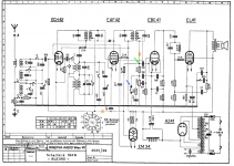
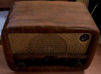
Recently I wanted to make myself a cheap guitar amplifier/combo of a kind for home practicing, so I found an old tube radio which isn't functional. This gives me most of the construction basis, together with a speaker, output stage, some preamplifier and a power supply, not mentioning the whole box. I have a bit of trouble understanding it though, so I'll attach the original schematic for it - see Sch_Original. I also added some markers which will come in handy next.
All the signal tubes (4 total) here have a rimlock base (B8A) (excluding the magic eye which is not relevant to my trouble) and I would really like to keep it that way. So, I found tube types that might be useful. I'll refer to each one later.
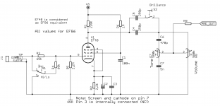
- EF40: a precedessor and equivalent of later EF86 - looking forward to an input stage with it;
ECC40 - instead of ECC83/12AX7 types and the one triode from EBC41;
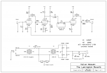
EF42 - for reverb circuit instead of EF80, explained later;
EL41 - output stage of below 5W.
Regarding schematic, firstly I would like to try and leave the EM34 for later usage as a crude VU meter, maybe adjust its sensitivity. Then, my instinct says to cut the connections marked with orange X-s and connect input jack to one of the points indicated by the green or blue arrow. By doing this I would probably have a functioning amplifier with a drawback of its frequency response. This gives me the circuit on Sch_1.
A question arises: What is actually happening here with all the capacitors, filtering and feedbacks and is it worth keeping for a guitar usage? I simulated this circuit with the triode only and it seems to alter bass response on low volume (5dB increased gain up to 300Hz), in the middle the frequency response is quite flat, and then it increases 300Hz-4kHz by 2dB on max volume (all values approximate - I'll skip the graphs for now).
Then, the input stage, where I somehow look towards pentode input. I probably can substitute EF86 with EF40, which is said to be a precedessor and almost equivalent tube - not, that I am right, but looking at the datasheets we are really close. The schematic for this stage, probably found by me long time ago from some other guitar amplifier, is most probably to be the one shown on Sch_2. On this part of my idea I hardly have any doubt, and if any, it's the R9 resistor value and further integration with reverb stage.
The reverb stage - I found this nice idea: LINK . Also attaching the schematic as Sch_Revb.
The first concern here is swapping EF80 for the EF42. Why EF42? - I tried to compare the tubes' Typical Characteristics and EF42 seemed to be a close one. Using it would probably need some components adjusting around it; it seems to be a basic pentode gain stage which should be even possible to recalculate. Am I right to this point?
Another trouble is, how to integrate it with the input stage? Am I correct when I think, I can 'delete' the input triode and connect the "Dwell" potentiometer after input stage? But what about the "Mix" potentiometer? EF40 (input stage) is cathode biased, so copy-cat-ing after the input triode from this design is a no-go. I wouldn't want to exceed 4 tubes in total because of the current draw from power transformer and rectifier tube, AND heater supply. Also, based on previous simulation, the EL41 needs a fairly big amplitude to drive it, so the reverb recovery triode probably won't do it. This is very troublesome for me and I'd be very thankful for any ideas.
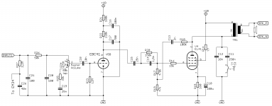
Next and possibly last is the power supply and output stage. I noticed that usually the screen grid (second) of output tube is connected through resistor in some way, supplying it with lower voltage. Should we alter it or leave as is? The EL41 tube datasheet says Vgs2 = Va = 250V for a SE class A amplifier - so maybe it's correct.
The matter of power supply is, most if not all tube designs use a multi stage filtering which also gives multiple voltages for respective gain stages. Should we leave it as is or change to "the standard"? I'm having in mind the AZ41 tube which is specified for output capacitor of 2x 50uF max only.
At the end I would expect the signal path to be: EF40>ECc40>EF42>Reverb>EcC40>EL41 with controls such as Volume, Tone (somewhere on the way, not necessarily with the input stage), Dwell+Mix and Master Volume (if it has any sense). The longer I look at it though, the more I doubt it is achieveable. Maybe I could squeeze somewhere a subminiature tube if another stage would be needed somewhere? Maybe a MOSFET in a place it won't alter the sound? No idea here. (wouldn't want any semiconductors though)
For any questions with actual sound, I'm looking for just a little distortion, but mostly clean sound. If the gain could be changed for more distorted sound with a switch, I'd surely take it! I'll also leave the original speaker in hope of some fancy "vintage" sound.
Let's also say I will not be using any old capacitors, as the original 70 years old ones need replacing just from looking at them. Also please do let me know, if I am forgetting something.
I will be plugging the radio and measuring its working conditions - voltages and currents - in a few days, so it will help in determining this project feasibility and basic parameters.
All kinds of help, whether it is a straight solution, example, suggestion or some article to read, will be greatly appreciated! In no means though I am expecting a ready fix and I'd rather learn than copy.
Many thanks to you all and everyone for any input to my post.
Cheers,
Jakub
I hope I found myself in the right place to talk about such ideas and obviously to ask questions in the search of answers and solutions. I'm happy to have found this forum.
I'm in my 20's doing some electronics as a part of my lifetime hobby. Usually it's digital, less analog and hardly ever tubes, so I'm not that experienced with them and usually can't understand the bigger theory. I have made a few amps, but these were more of a "kit" than "design".
~~~
Recently I wanted to make myself a cheap guitar amplifier/combo of a kind for home practicing, so I found an old tube radio which isn't functional. This gives me most of the construction basis, together with a speaker, output stage, some preamplifier and a power supply, not mentioning the whole box. I have a bit of trouble understanding it though, so I'll attach the original schematic for it - see Sch_Original. I also added some markers which will come in handy next.
All the signal tubes (4 total) here have a rimlock base (B8A) (excluding the magic eye which is not relevant to my trouble) and I would really like to keep it that way. So, I found tube types that might be useful. I'll refer to each one later.
- EF40: a precedessor and equivalent of later EF86 - looking forward to an input stage with it;
ECC40 - instead of ECC83/12AX7 types and the one triode from EBC41;
EF42 - for reverb circuit instead of EF80, explained later;
EL41 - output stage of below 5W.
Regarding schematic, firstly I would like to try and leave the EM34 for later usage as a crude VU meter, maybe adjust its sensitivity. Then, my instinct says to cut the connections marked with orange X-s and connect input jack to one of the points indicated by the green or blue arrow. By doing this I would probably have a functioning amplifier with a drawback of its frequency response. This gives me the circuit on Sch_1.
A question arises: What is actually happening here with all the capacitors, filtering and feedbacks and is it worth keeping for a guitar usage? I simulated this circuit with the triode only and it seems to alter bass response on low volume (5dB increased gain up to 300Hz), in the middle the frequency response is quite flat, and then it increases 300Hz-4kHz by 2dB on max volume (all values approximate - I'll skip the graphs for now).
Then, the input stage, where I somehow look towards pentode input. I probably can substitute EF86 with EF40, which is said to be a precedessor and almost equivalent tube - not, that I am right, but looking at the datasheets we are really close. The schematic for this stage, probably found by me long time ago from some other guitar amplifier, is most probably to be the one shown on Sch_2. On this part of my idea I hardly have any doubt, and if any, it's the R9 resistor value and further integration with reverb stage.
The reverb stage - I found this nice idea: LINK . Also attaching the schematic as Sch_Revb.
The first concern here is swapping EF80 for the EF42. Why EF42? - I tried to compare the tubes' Typical Characteristics and EF42 seemed to be a close one. Using it would probably need some components adjusting around it; it seems to be a basic pentode gain stage which should be even possible to recalculate. Am I right to this point?
Another trouble is, how to integrate it with the input stage? Am I correct when I think, I can 'delete' the input triode and connect the "Dwell" potentiometer after input stage? But what about the "Mix" potentiometer? EF40 (input stage) is cathode biased, so copy-cat-ing after the input triode from this design is a no-go. I wouldn't want to exceed 4 tubes in total because of the current draw from power transformer and rectifier tube, AND heater supply. Also, based on previous simulation, the EL41 needs a fairly big amplitude to drive it, so the reverb recovery triode probably won't do it. This is very troublesome for me and I'd be very thankful for any ideas.
Next and possibly last is the power supply and output stage. I noticed that usually the screen grid (second) of output tube is connected through resistor in some way, supplying it with lower voltage. Should we alter it or leave as is? The EL41 tube datasheet says Vgs2 = Va = 250V for a SE class A amplifier - so maybe it's correct.
The matter of power supply is, most if not all tube designs use a multi stage filtering which also gives multiple voltages for respective gain stages. Should we leave it as is or change to "the standard"? I'm having in mind the AZ41 tube which is specified for output capacitor of 2x 50uF max only.
At the end I would expect the signal path to be: EF40>ECc40>EF42>Reverb>EcC40>EL41 with controls such as Volume, Tone (somewhere on the way, not necessarily with the input stage), Dwell+Mix and Master Volume (if it has any sense). The longer I look at it though, the more I doubt it is achieveable. Maybe I could squeeze somewhere a subminiature tube if another stage would be needed somewhere? Maybe a MOSFET in a place it won't alter the sound? No idea here.
(wouldn't want any semiconductors though)For any questions with actual sound, I'm looking for just a little distortion, but mostly clean sound. If the gain could be changed for more distorted sound with a switch, I'd surely take it! I'll also leave the original speaker in hope of some fancy "vintage" sound.
Let's also say I will not be using any old capacitors, as the original 70 years old ones need replacing just from looking at them. Also please do let me know, if I am forgetting something.
I will be plugging the radio and measuring its working conditions - voltages and currents - in a few days, so it will help in determining this project feasibility and basic parameters.
All kinds of help, whether it is a straight solution, example, suggestion or some article to read, will be greatly appreciated! In no means though I am expecting a ready fix and I'd rather learn than copy.
Many thanks to you all and everyone for any input to my post.
Cheers,
Jakub
Attachments
Hi Jakub, you are off to a flying start, which is great to see.
Can I suggest to keep the initial hardware changes to as minimal as practical in order to get some signal through all the available valve sockets (with changed valves to suit your target amp). Finessing part values and including circuit 'nice to haves' are better left to after you have basic operation and understanding in hand.
Vintage equipment is imho the best initial platform to learn from (especially when low in cost). The link below may help you check on safety and risks, and what you may be getting in to.
I would suggest not tearing apart the hardware until you have a good awareness of what you will initially do, and can safely test what you have. From experience I and others can suggest what you wouldn't need to keep, and you are nearly at that point by looking at your proposed schematics.
https://www.dalmura.com.au/static/Renovating%20PA%20amps.pdf
Ciao, Tim
Hi Tim,
Thank you for your reply!
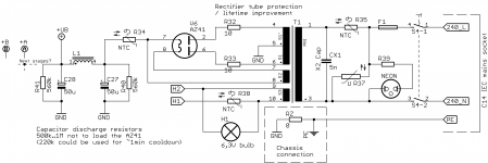
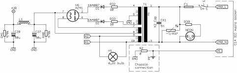
I must say that is A LOT of reading and useful information, thank you very much for this. At the same time I already have thought of at least few if not several matters mentioned in this article. You also reminded me about few tips from my other amplifier regarding power supply, so I took some time and drew them in. Some of them I'd only include after adequate testing, of course, but initial schematic would be as in attached Sch_Supply. The X2 capacitor is placed to comply with the original schematic.
I also share your suggestion to start only with the required minimum to get some sound through and that's what I intend to do first. I am not afraid to start and am mostly sure of this first step - cut the connections I mentioned and plug in a signal source - but some guide on the next things would be great. For example I am still very curious about the things in original schematic I mentioned.
Maybe my questions will clarify in some time and I understand they are kind of big now - but at the same time, to hear my thought process is quite correct or just not bad would really eager me up on future work and actually help in knowing and understanding what I'm doing (instead of wandering around in total darkness).
Meanwhile I also came up with the idea to make "Reverb Volume" (usually called "Wet") instead of "Mix" as it seems easier to do and probably is more versatile. No need to worry where to connect the loose terminal of "Mix" potentiometer. Just worry about summing with clean ("Dry") signal so that "Dry" and "Wet" potentiometers do not interfere with each other.
Any modifications regarding final sound and functionality are of course to be done in small steps on previously tested and working part of circuit. (But I'll still buy the reverb tank soon)
The article also got my attention on the "I will be plugging the radio and measuring(...)" - that it would be a bit silly to power it "as is". I don't have a variac but there's nothing that few incandescent bulbs in series cannot do. Also I am aware of handling things with high voltages, so I shall be safe.
Much thanks for further help!
Cheers,
Jakub
Thank you for your reply!
I must say that is A LOT of reading and useful information, thank you very much for this. At the same time I already have thought of at least few if not several matters mentioned in this article. You also reminded me about few tips from my other amplifier regarding power supply, so I took some time and drew them in. Some of them I'd only include after adequate testing, of course, but initial schematic would be as in attached Sch_Supply. The X2 capacitor is placed to comply with the original schematic.
I also share your suggestion to start only with the required minimum to get some sound through and that's what I intend to do first. I am not afraid to start and am mostly sure of this first step - cut the connections I mentioned and plug in a signal source - but some guide on the next things would be great. For example I am still very curious about the things in original schematic I mentioned.
Maybe my questions will clarify in some time and I understand they are kind of big now - but at the same time, to hear my thought process is quite correct or just not bad would really eager me up on future work and actually help in knowing and understanding what I'm doing (instead of wandering around in total darkness).
Meanwhile I also came up with the idea to make "Reverb Volume" (usually called "Wet") instead of "Mix" as it seems easier to do and probably is more versatile. No need to worry where to connect the loose terminal of "Mix" potentiometer. Just worry about summing with clean ("Dry") signal so that "Dry" and "Wet" potentiometers do not interfere with each other.
Any modifications regarding final sound and functionality are of course to be done in small steps on previously tested and working part of circuit. (But I'll still buy the reverb tank soon)
The article also got my attention on the "I will be plugging the radio and measuring(...)" - that it would be a bit silly to power it "as is". I don't have a variac but there's nothing that few incandescent bulbs in series cannot do.
Also I am aware of handling things with high voltages, so I shall be safe.Much thanks for further help!
Cheers,
Jakub
Attachments
This is a great little project! Super interested to see how it goes.
I would start by getting everything else working well, and worry about adding the reverb last. You might look at a Princeton Reverb AA1164 schematic for a different approach from the mix potentiometer in your schematic.
I would start by getting everything else working well, and worry about adding the reverb last. You might look at a Princeton Reverb AA1164 schematic for a different approach from the mix potentiometer in your schematic.
Hi!
Happy to see some increasing interest.
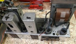
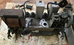
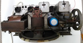
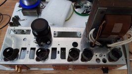
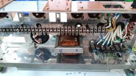
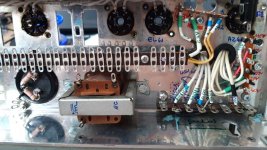
Attaching some current and earlier pictures of the inside workings. Currently I have removed the old power cord and am brainstorming on how to replace the mains voltage selector - which is like a bare, live wire without protection - and add an IEC mains socket without being invasive and destructive. All the paper-wax capacitors leak wax and some big one even seems to had had boiled itself at some point. The tubes are in a safe place and look quite okay. Of course I have documented the disassembly to this point.
I probably won't be keeping the front panel, as unfortunately it got damaged at some point, but will try to keep the color scheme. There's a lot of visual work also.
I saw the Princeton solution, it might save me a potentiometer - I'll surely consider it.
Thank you for your suggestions - I really appreciate it and am looking forward to even more. (I'm still curious about the matters from my initial post.) I might put the work on hold until I get the speaker back though, but I'll keep you updated.
Cheers,
Jakub
Happy to see some increasing interest.
I have already started some disassembly and the speaker went to restoration, but hey, why not.A picture of the insides of the amp might be in order.
Attaching some current and earlier pictures of the inside workings. Currently I have removed the old power cord and am brainstorming on how to replace the mains voltage selector - which is like a bare, live wire without protection - and add an IEC mains socket without being invasive and destructive. All the paper-wax capacitors leak wax and some big one even seems to had had boiled itself at some point. The tubes are in a safe place and look quite okay. Of course I have documented the disassembly to this point.I probably won't be keeping the front panel, as unfortunately it got damaged at some point, but will try to keep the color scheme. There's a lot of visual work also.
I saw the Princeton solution, it might save me a potentiometer - I'll surely consider it.
Thank you for your suggestions - I really appreciate it and am looking forward to even more.
(I'm still curious about the matters from my initial post.) I might put the work on hold until I get the speaker back though, but I'll keep you updated.Cheers,
Jakub
Attachments
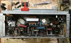
It does look circa 1950, based on many of the resistors and the use of an electromagnet speaker, and that correlates with the schematic 1953 date.
My view would be to test the power transformer for secondary heater voltages to get them ok, given it seems like you have some primary taps? Then insulate unused primary taps and try and shoe-horn in an IEC socket/fuse/switch combo, as the safest way to minimise AC primary wiring and interconnects and parts. Adding additional primary parts like NTC and cap and double pole mains switch are imho superfluous, and a safety risk, and just splay out high voltage hum fields in a small chassis (ie. locating the mains socket/etc should aim to separate and localise any mains wiring to just one small region).
As the rectifier valve may be difficult to replace, and may be aging, I'd recommend including the ss diode modification to avoid a poor valve diode from taking out the power transformer, and to allow a longer working life of the valve.
It's well worth going through the PSUD2 process of checking your power transformer is ok for the AZ41 and 50uF of cap.
As there is no feedback from the speaker side, then I'd recommend removing the EL41 anode hf filtering and feedback - radio's typically had heavy treble filtering to remove inter-station static and noise - and the close proximity of parts could easily lead to inadvertent feedback and possibly high frequency oscillation. The screen connection to the CLC filtered B+ is fine, and about the only addition could be a screen stopper (as you've shown) if you overdrive the class A output.
The EBC41 has a lot of filtering circuitry that wouldn't be needed imho. The 2x 100pF and 50k at the input are just hf filtering. The volume pot has tone tap which is no issue to leave initially, but may show up in a non-flat frequency response. The triode is grid leak biased which could be a hassle for you - the 12M grid leak likely needs to be tweaked to get the anode idle voltage to an ok level, and it may cause an overdrive distortion depending on your input signal level. The anode loading is also filtered by the 700pF which could be removed. The coupling network has a 1.5nF 150k bass shaper which could be removed for starters.
I'd suggest using a simple RC dropper-filter for each preamp valve stage's B+ supply - perhaps aim to include at least 10uF and 10k for starters. Until you know the main B+ voltage under output stage idle, and the idle current of the preamp stages, the voltages are somewhat unknown.
Last edited:
Hi!
I was busy with other work throughout the weekend, so with a bit of a delay, thank you all!
Regarding the supply rectifier, most probably I will leave it in tube only form, eventually with some protection to it. I have searched for replacement tubes and I can get a NOS AZ41 in a fairly reasonable price, so no worries with running on the old tube with unknown performance. The same applies to other tubes and I think it's great.
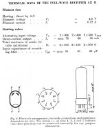
I have checked and made a rough calculations of the max supply current expected on a finished circuit (ie. all stages in the way I would want them) and it rounded to 65mA, while the rectifier tube allows for 70mA as long as the voltage is under 300V. I have also tried to obtain something with PSUD2 as mentioned, but all the datasheets available for the AZ41 specify just the basic working parameters, without the "Absolute Maximum" part as in some newer tubes. Didn't stop there of course and tried it with some other tubes with similar (and even worse) current specified. Assuming we're looking for 250V at the output with 65mA of current, regadless of the tube selected I got the continuous peaks below the max current allowed per single anode: about 20-28mA vs the 35mA max. Also the AZ11 is said to be AZ41 precedessor and the results with it also look okay to me. See attachments. So, at the end of the day, it might allow to squeeze another triode, but first we have some heater and the actual supply to check - above are just assumptions. I'm sorry I still don't have it, I want to make a little "debug" device first, which would let me regulate the mains input power and allow for a controlled test environment.
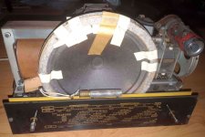
I see the perspective on previous photos got misleading with the speaker, which isn't electrodynamic (I wish I had one!), but a standard Alnico one with the output transformer mounted on it. Quite an idea in terms of squeezing much stuff in limited space.
@throbbins - thank you very much for your reply, life seems easier now. It also put me more towards not keeping the voltage selector in any form (I wanted to use a tube socket with isolated captive jumper thing), though I have trouble imagining 4 of 5 taps total, though isolated, being loose. But besides, there is no need for me to change it at any time, so why not.
I'd gladly use a combo IEC socket if not the fact I once saw one with the fuse connected on the neutral terminal, which as far as I know, is a very bad thing and is a safety risk. Since then I avoid them at all cost. Keeping the power switch on rear is a thing, though.
I removed the unnecessary components on my schematic according to what you have said and now it surely looks the way I'm used to.
Let me know if I'm missing something.
A side note - I expect to get a little less active in following days as life always happens. I'll try my best though to keep this place active more or less, regardless of my daily work. Thank you for understanding.
As always, much thanks and appreciation to everybody for any kind of help or reply.
Cheers,
Jakub
I was busy with other work throughout the weekend, so with a bit of a delay, thank you all!
Regarding the supply rectifier, most probably I will leave it in tube only form, eventually with some protection to it. I have searched for replacement tubes and I can get a NOS AZ41 in a fairly reasonable price, so no worries with running on the old tube with unknown performance. The same applies to other tubes and I think it's great.
I have checked and made a rough calculations of the max supply current expected on a finished circuit (ie. all stages in the way I would want them) and it rounded to 65mA, while the rectifier tube allows for 70mA as long as the voltage is under 300V. I have also tried to obtain something with PSUD2 as mentioned, but all the datasheets available for the AZ41 specify just the basic working parameters, without the "Absolute Maximum" part as in some newer tubes. Didn't stop there of course and tried it with some other tubes with similar (and even worse) current specified. Assuming we're looking for 250V at the output with 65mA of current, regadless of the tube selected I got the continuous peaks below the max current allowed per single anode: about 20-28mA vs the 35mA max. Also the AZ11 is said to be AZ41 precedessor and the results with it also look okay to me. See attachments. So, at the end of the day, it might allow to squeeze another triode, but first we have some heater and the actual supply to check - above are just assumptions. I'm sorry I still don't have it, I want to make a little "debug" device first, which would let me regulate the mains input power and allow for a controlled test environment.
I see the perspective on previous photos got misleading with the speaker, which isn't electrodynamic (I wish I had one!), but a standard Alnico one with the output transformer mounted on it. Quite an idea in terms of squeezing much stuff in limited space.
@throbbins - thank you very much for your reply, life seems easier now.
It also put me more towards not keeping the voltage selector in any form (I wanted to use a tube socket with isolated captive jumper thing), though I have trouble imagining 4 of 5 taps total, though isolated, being loose. But besides, there is no need for me to change it at any time, so why not.I'd gladly use a combo IEC socket if not the fact I once saw one with the fuse connected on the neutral terminal, which as far as I know, is a very bad thing and is a safety risk. Since then I avoid them at all cost. Keeping the power switch on rear is a thing, though.
I removed the unnecessary components on my schematic according to what you have said and now it surely looks the way I'm used to.
Let me know if I'm missing something.
A side note - I expect to get a little less active in following days as life always happens. I'll try my best though to keep this place active more or less, regardless of my daily work. Thank you for understanding.
As always, much thanks and appreciation to everybody for any kind of help or reply.
Cheers,
Jakub
Attachments
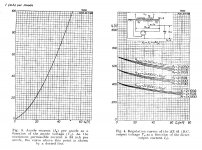
PSUD2 can be used to deduce the continuous peak and the surge peak current levels for the datasheet scenarios (given that the AZ41 datasheet doesn't state those peak current levels.
For example, using an AZ1 diode and 300Vrms secondary with 100ohm effective resistance and a 50uF cap and 70mA load (4.5kohm), the output voltage is about 318V, and the simulated surge peak is 1.2A, and continuous peak is 0.25A.
Assuming you want to cover a 70mA load with the AZ41 and a 50uF cap and the 230V 85 ohm transformer parameters, then the load is 3.3k, and the surge peak is 0.9A, and continuous peak is 0.23A, so they appear to be just under the diode ratings with that transformer (so no need for additional series resistance). You may notice that increasing cap to 100uF doesn't take you over the nominal peak limits, which gives some headroom as cap tolerance or only having say a 60uF cap may take you over 50uF. Given the power supply has a CLC filter, then there is no need to push for a high first cap value.
If you were keen you could measure the choke inductance (eg. using this technique), and then use PSUD2 again to check the B+ voltage and ripple you may end up with in the amp.
Such an IEC combo with fused neutral would indeed be illegal in some countries - for AC mains it is worth getting compliant parts and cables.
Last edited:
Could just put the SS diodes in series of the tube rectifier. This would protect the PT in event of a failure.
Yup. As recommended by Rob Robinette and in the Immortal Amp articles.
If you haven't already, spend some time reading through RR. Particularly on safety.
P.s. assume any electrolitic caps are dry or at least in need of reforming.
Hi!
I'm back and very much alive My apologies for such long break.
I was waiting for my RLC tester to arrive and couldn't find any free time (also my beloved 7-year old laptop is burning out and needs to get replaced, so there's that), so all the work was on hold. Meantime I wanted polish up the looks of the woodden enclosure but that failed too. (Any alternatives for the old shellac polish?)
I see the following recommendation appearing more than once:
So, if you insist, then alright Maybe it is a way better idea, since we're working with older tubes and equipment than the current tube amps. But still then, why those don't incorporate such preventive measures? I really wanted to keep any SS devices out of it though, as it is what I'm familiar with when building tube circuits, yet there's nothing worse than ordering a custom power transformer.
Regarding protection connected with the power supply part, I was thinking if placing a fuse on the center tap of the transformer would do any bad? Besides losing ground, when the rectifier tube fails and blows the fuse, the current will have nowhere to go and overall it should be quite safe. I see some issues with it though, so I'm just wondering. Solves the core magnetisation problem though.
Since I haven't disassembled the radio completely yet, would there be any audio use for the tuning capacitor? I'm not feeling good with ruining its assembly, at least currently. If I do though, it will give me a lot of space for other components, mainly potentiometers. Generally I thought about using it for a tone or presence control. It has two identical sections - I measured one and it goes to about 680pF max, but maybe the meter isn't so precise here. Together it might have somewhere around 1-1,5nF.
So, here I wanted to show you some measurements, but apart some winding resistances, I still haven''t managed to power it up, because of the literal mess and 70-year old dust inside which I want to get rid of. The transformer leads also could use some reorganisation and protection from breaking off. Too bad, as I recently have finished the test desk (mains socket + few switchable incandescent bulbs in series and a current meter) and I was really looking forward to it. So maybe I'll leave a question with the resistances for you to verify for now:
R_primary = 48,8 Ohms (on 240V tap)
R_secondary ("B+") = 541 Ohms total (266/275 ohms each half)
R_ht_5V = 0,3 Ohms
R_ht_6.3V = 0,2 Ohms
Does this seem anything close to alright to you? I probably should mention the radio also had a blown fuse, so I feel a bit afraid there might be something wrong.
As for other accomplishments - for fun I have also measured the old capacitors, especially the one that looked like it had been boiling...and yeah, they are dead. Good thing though the dual 50uF cap seems to be okay! Low ESR (under 0,5 ohm), capacitance in reasonable limits and such. Maybe I'll try to format it a bit though.
I am also awaiting some spare tubes to arrive, as I do not know the condition of the original ones and it will probably be safer with newer ones.
I'm looking forward to your replies and in meantime, I'll do some more disassembly and cleaning, then maybe rebuild and test the output stage using just the tubes required for it. The speaker returned from renovation and oh does it look gorgeous.
I'll do my best to not keep you waiting.
Thank you all for your kindest help, I appreciate it in every bit!
Cheers,
Jakub
I'm back and very much alive
My apologies for such long break.I was waiting for my RLC tester to arrive and couldn't find any free time (also my beloved 7-year old laptop is burning out and needs to get replaced, so there's that), so all the work was on hold. Meantime I wanted polish up the looks of the woodden enclosure but that failed too. (Any alternatives for the old shellac polish?)
I see the following recommendation appearing more than once:
Could just put the SS diodes in series of the tube rectifier. This would protect the PT in event of a failure.
So, if you insist, then alright
Maybe it is a way better idea, since we're working with older tubes and equipment than the current tube amps. But still then, why those don't incorporate such preventive measures? I really wanted to keep any SS devices out of it though, as it is what I'm familiar with when building tube circuits, yet there's nothing worse than ordering a custom power transformer.Regarding protection connected with the power supply part, I was thinking if placing a fuse on the center tap of the transformer would do any bad? Besides losing ground, when the rectifier tube fails and blows the fuse, the current will have nowhere to go and overall it should be quite safe. I see some issues with it though, so I'm just wondering. Solves the core magnetisation problem though.
Since I haven't disassembled the radio completely yet, would there be any audio use for the tuning capacitor? I'm not feeling good with ruining its assembly, at least currently.
If I do though, it will give me a lot of space for other components, mainly potentiometers. Generally I thought about using it for a tone or presence control. It has two identical sections - I measured one and it goes to about 680pF max, but maybe the meter isn't so precise here. Together it might have somewhere around 1-1,5nF.So, here I wanted to show you some measurements, but apart some winding resistances, I still haven''t managed to power it up, because of the literal mess and 70-year old dust inside which I want to get rid of. The transformer leads also could use some reorganisation and protection from breaking off. Too bad, as I recently have finished the test desk (mains socket + few switchable incandescent bulbs in series and a current meter) and I was really looking forward to it. So maybe I'll leave a question with the resistances for you to verify for now:
R_primary = 48,8 Ohms (on 240V tap)
R_secondary ("B+") = 541 Ohms total (266/275 ohms each half)
R_ht_5V = 0,3 Ohms
R_ht_6.3V = 0,2 Ohms
Does this seem anything close to alright to you? I probably should mention the radio also had a blown fuse, so I feel a bit afraid there might be something wrong.
As for other accomplishments - for fun I have also measured the old capacitors, especially the one that looked like it had been boiling...and yeah, they are dead. Good thing though the dual 50uF cap seems to be okay!
Low ESR (under 0,5 ohm), capacitance in reasonable limits and such. Maybe I'll try to format it a bit though.I am also awaiting some spare tubes to arrive, as I do not know the condition of the original ones and it will probably be safer with newer ones.
I'm looking forward to your replies and in meantime, I'll do some more disassembly and cleaning, then maybe rebuild and test the output stage using just the tubes required for it. The speaker returned from renovation and oh does it look gorgeous.
I'll do my best to not keep you waiting.
Thank you all for your kindest help, I appreciate it in every bit!
Cheers,
Jakub
Maybe the latest amps do? The technique was not well known more than 10 years ago. Manufacturers often don't include extra effort unless their warranty or image is suffering.So, if you insist, then alright
https://www.dalmura.com.au/static/Valve%20amp%20fusing.pdfRegarding protection connected with the power supply part, I was thinking if placing a fuse on the center tap of the transformer would do any bad? Besides losing ground, when the rectifier tube fails and blows the fuse, the current will have nowhere to go and overall it should be quite safe. I see some issues with it though, so I'm just wondering.
YesR_primary = 48,8 Ohms (on 240V tap)
R_secondary ("B+") = 541 Ohms total (266/275 ohms each half)
R_ht_5V = 0,3 Ohms
R_ht_6.3V = 0,2 Ohms
Does this seem anything close to alright to you?
Hello all!
Firstly, I know it might look like the thread is dead, but I'm still working on it, just slowly - job, university etc. aside. It is officially a year since I obtained the radio.
Secondly, I finally found the time to wire up the transformer and measure it. Funny thing though is, I remember that, while checking it with ohmmeter right after disassembly, it had two (separate) secondary windings for the B+, instead of one with center tap - which would give the four leads some sense. Well, now I measure one winding with a center tap and a spare lead instead, but it is all working. Is my mind sane yet? I'm really confused, but if it works, it works - right? It was during or after I did some work with the transformer, so the leads wouldn't break at the winding ends/transformer body - but still, now that it works, am I wrong to think it had two secondary HV windings? (No indication of that in the available schematic)
My multimeter was a little bit hesistant on giving a stable measurement, so the results are assumed, while actually fluctuating +/- 0.5V. Current load is determined by what resistors I had to load the transformer. The transformer was connected through 240V (highest) primary tap. Findings below.
V_ht_4V = 4V under 300mA load
V_ht_6.3V = 6.3V under 1A load
V_B+ = >300V no load, 299V under 30mA
(All AC)
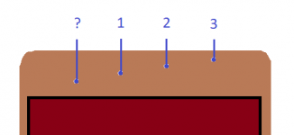
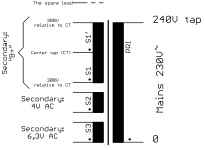
Spare lead: 0.5V to 0.7V with negative probe on secondary winding center tap lead, otherwise no internal connection found. 0V when unpowered. A screen connection maybe? Should I (not) connect it and where? I'll try to find the disassembly photos I have taken, but I'm not sure if that lead was distinguished in any way. It surely is wired the furthest/deepest into the transformer (aside heater windings), that is, if you had layers, this lead comes out first, then the B+ wiring 1, 2 (center) and 3 leads. I made a picture for better understanding; transformer core ommitted.
For a full view, the 6.3V winding seems to be first, then the B+ and all, and 4V winding is the last.
I didn't say a thing last time, so trobbins, thank you as always for your support! I have figured out my (weird) ideas and do not wish to continue them I have even learnt that a standby switch is very unnecessary, which now is a good thing for me, also less hassle.
I will upload some photos with the progress when I get some serious wires inside. Now I have cleaned the chassis, made a place for the new supply capacitor and attached it, mounted some terminal strips, cut and machined some textolite to adapt some connectors to the original holes, installed a fuse and wired the heaters and earth connection. Now thinking of powering it with rectifier tube - and wondering, how to load it properly (so it won't just be idle)? Assuming:
As always, thank you all for your interest and help, I do appreciate it!
Cheers,
Jakub
Firstly, I know it might look like the thread is dead, but I'm still working on it, just slowly - job, university etc. aside. It is officially a year since I obtained the radio.
Secondly, I finally found the time to wire up the transformer and measure it. Funny thing though is, I remember that, while checking it with ohmmeter right after disassembly, it had two (separate) secondary windings for the B+, instead of one with center tap - which would give the four leads some sense. Well, now I measure one winding with a center tap and a spare lead instead, but it is all working. Is my mind sane yet? I'm really confused, but if it works, it works - right? It was during or after I did some work with the transformer, so the leads wouldn't break at the winding ends/transformer body - but still, now that it works, am I wrong to think it had two secondary HV windings? (No indication of that in the available schematic)
My multimeter was a little bit hesistant on giving a stable measurement, so the results are assumed, while actually fluctuating +/- 0.5V. Current load is determined by what resistors I had to load the transformer. The transformer was connected through 240V (highest) primary tap. Findings below.
V_ht_4V = 4V under 300mA load
V_ht_6.3V = 6.3V under 1A load
V_B+ = >300V no load, 299V under 30mA
(All AC)
Spare lead: 0.5V to 0.7V with negative probe on secondary winding center tap lead, otherwise no internal connection found. 0V when unpowered. A screen connection maybe? Should I (not) connect it and where? I'll try to find the disassembly photos I have taken, but I'm not sure if that lead was distinguished in any way. It surely is wired the furthest/deepest into the transformer (aside heater windings), that is, if you had layers, this lead comes out first, then the B+ wiring 1, 2 (center) and 3 leads. I made a picture for better understanding; transformer core ommitted.
For a full view, the 6.3V winding seems to be first, then the B+ and all, and 4V winding is the last.
I didn't say a thing last time, so trobbins, thank you as always for your support! I have figured out my (weird) ideas and do not wish to continue them
I have even learnt that a standby switch is very unnecessary, which now is a good thing for me, also less hassle.I will upload some photos with the progress when I get some serious wires inside. Now I have cleaned the chassis, made a place for the new supply capacitor and attached it, mounted some terminal strips, cut and machined some textolite to adapt some connectors to the original holes, installed a fuse and wired the heaters and earth connection. Now thinking of powering it with rectifier tube - and wondering, how to load it properly (so it won't just be idle)? Assuming:
- 300V AC -> 423 DC after rectification (ideal)
- AZ41 is specified for 60-70mA output
As always, thank you all for your interest and help, I do appreciate it!
Cheers,
Jakub
Attachments
Hardly. Compared to some of my projects.....Firstly, I know it might look like the thread is dead,
Jakub, perhaps a good idea to link to a schematic when giving measurement values, and make sure there is a direct association between schematic rail identifiers and your text.
I'd suggest you need to confirm all the power transformer leads - and not just assume. It can be difficult to confirm a screen - one indicator is to measure its capacitance relative to primary and secondary taps as it will have a higher capacitance when measuring to the tap associated with nearest winding layers - another indicator is that there is infinite insulation resistance between it and any other winding with at least 1kVdc applied - another indicator if you can see where the wire enters the winding is that it goes somewhere between the primary and secondary exit wires. Perhaps label your diagram of where the tap wires exit, and include where the core is and primary winding taps and the other windings.
Perhaps best to start with a schematic of what you have, or will have, in place, and some photos - as a way of trying to confirm you have a safe initial power supply to think about energising.
Perhaps identify your multimeter and check if it measures rms voltage and its resolution and accuracy, and present results as eg. 6.3Vrms (accuracy 0.1Vrms - resolution 0.01Vrms) so we get some confidence in your reported results.
Last edited:
Hello!
Thank you for replies! I wanted to post an update yesterday, but forgot to, due to actually working on the radio/amp. I figured out the mystery transformer lead purpose, thanks to my notes on the original schematic, when I was disassembling it: it was connected together with the center tap lead of the secondary winding. With that in mind, I'm not going to do otherwise and I'll solder it accordingly. Besides, it seems logical, because it's a connection to ground and earth, so it nearly must be some kind of screen connection and I must have been not focused enough on the measurements back then or did them before any disassembly, thus my confusion.
Also, I checked it against the secondary windings, using the cheap and popular RLC meter/tester, which surely enough indicated some capacitance, ranging 64pF to 580pF - lowest on the 4V heater winding, highest on one end of the B+ winding, which I can probably assume is the winding start (also on one end of the primary).
I'm attaching the transformer configuration for clearence with my previous post. Hope it will clear it a bit. I'd rather not draw another weird diagrams, but what I figured out by now would be the below written description.
So, if we have layers on the transformer, having in mind the capacitance readings (higher=closer), it seems to be wound as follows:
[center core column] || {Primary start->primary end*} | {Screen} | {Sec.B+ start->CT->end} | {6,3V start->end} | {4V start->end} || [external insulation]
* - 240V tap.
4V and 6,3V are most likely one layer windings.
There is also ca. 105pF capacitance to the core, but do have in mind the transformer is already mounted and united with the chassis. Hoping it does not mean a bad thing. I know an insulation tester would be great, yet I don't have any ways or means to get such thing.
Screen confirmed, then?
) and standard heater voltage will never become being marked as 6.[random value] V (you know what I mean).
I think that's all for now.
Of course, including some photos, which can also be considered as a sneak peek of current work in progress.
Encouraging, not that I don't know the struggle
All the best,
Jakub
Thank you for replies! I wanted to post an update yesterday, but forgot to, due to actually working on the radio/amp. I figured out the mystery transformer lead purpose, thanks to my notes on the original schematic, when I was disassembling it: it was connected together with the center tap lead of the secondary winding. With that in mind, I'm not going to do otherwise and I'll solder it accordingly. Besides, it seems logical, because it's a connection to ground and earth, so it nearly must be some kind of screen connection and I must have been not focused enough on the measurements back then or did them before any disassembly, thus my confusion.
Also, I checked it against the secondary windings, using the cheap and popular RLC meter/tester, which surely enough indicated some capacitance, ranging 64pF to 580pF - lowest on the 4V heater winding, highest on one end of the B+ winding, which I can probably assume is the winding start (also on one end of the primary).
I'm attaching the transformer configuration for clearence with my previous post. Hope it will clear it a bit. I'd rather not draw another weird diagrams, but what I figured out by now would be the below written description.
So, if we have layers on the transformer, having in mind the capacitance readings (higher=closer), it seems to be wound as follows:
[center core column] || {Primary start->primary end*} | {Screen} | {Sec.B+ start->CT->end} | {6,3V start->end} | {4V start->end} || [external insulation]
* - 240V tap.
4V and 6,3V are most likely one layer windings.
There is also ca. 105pF capacitance to the core, but do have in mind the transformer is already mounted and united with the chassis. Hoping it does not mean a bad thing. I know an insulation tester would be great, yet I don't have any ways or means to get such thing.
I would say so, most probably.another indicator if you can see where the wire enters the winding is that it goes somewhere between the primary and secondary exit wires
Screen confirmed, then?
I powered the transformer up alone in a possibly controlled environment with protection and somebody else close. But sure, now that it is mounted to the chassis, it's a different story. I am waiting for the mains socket and some wires to arrive, so that's all I can show you now and I will not be turning it on until I can properly wire it inside. What I did though with the transformer and also inside:Perhaps best to start with a schematic of what you have, or will have, in place, and some photos - as a way of trying to confirm you have a safe initial power supply to think about energising.
- Insulated twice the existing, old, fragile leads with heat shrink tubing and silicone/glass braid - not only great insulation, but also restricts the bend radius of the wires
- Secured the winding wires with silicone, so they don't bend and possibly break right at the transformer body
- Marked each transformer wire at its end, heat shrink tube'd and color-coded accordingly to original insulation colours with what I currently had
- Inside: somewhat good, somewhat bad, but there is no floating wire from the transformer, every single one has its place on a terminal strip;
- Terminal strips mounted with locking washers, loctite could be added;
- Earth connection will be close to mains socket;
- Supply ground is close to power supply capacitor(s) - it is the only way to do with that chassis layout, unfortunately - to separate Earth terminal from Ground terminal
My multimeter - UNI-T UT30D - is probably half as old as me, 13 years I think? I found it's manual and it says:Perhaps identify your multimeter and check if it measures rms voltage and its resolution and accuracy, and present results as eg. 6.3Vrms (accuracy 0.1Vrms - resolution 0.01Vrms) so we get some confidence in your reported results.
- Accuracy is described as +/- 1.2%+10 on 200 and 500V AC
- Display: RMS of Sine Wave Value (Average Value)
What can I say, I wanted to update the thread so badly that I forgot about the basic things an engineer should do. I try to keep the identifiers consistent though, B+ would never be Z+ (or Ó+Jakub, perhaps a good idea to link to a schematic when giving measurement values, and make sure there is a direct association between schematic rail identifiers and your text.
) and standard heater voltage will never become being marked as 6.[random value] V (you know what I mean).I think that's all for now.
Of course, including some photos, which can also be considered as a sneak peek of current work in progress.
Hardly. Compared to some of my projects.....
Encouraging, not that I don't know the struggle
All the best,
Jakub
Attachments

Well done for taking due care - imho it is always worth the time and effort to be diligent during preparations, and that includes forcing yourself to 'write up' the process and then self-review and try and identify any aspects you haven't quite sorted out properly.
That meter is somewhat poor for making ACV measurements under say 10V. A 4V reading has a 0.1V resolution but +/-1V accuracy, and is not true-rms.
That meter is somewhat poor for making ACV measurements under say 10V. A 4V reading has a 0.1V resolution but +/-1V accuracy, and is not true-rms.
Thank you! I do what I can to do my best
And well, looking at that multimeter manual made me think I might need a better one. I might try to do some measurements at work later, where I have, supposedly, something better. This will wait of course, until I have the proper mains socket and wires on hand - 2 weeks, best case.
Meanwhile, I have been thinking on this troubling matter of power supply voltage and I think I'd use some help on this one. It will be very important later, when I will start building the initial output and preamp stages.
Step 1.
Assuming - I think we can - the AC output voltage from transformer is around 300V RMS AC.
Then, with ideal rectifier, we can estimate the rectified DC voltage by multiplying the AC value by 1.41, which gives us roughly 423V. We hardly have an ideal rectifier, so, I don't know, let's take a wild guess and substract something down to around 350V.
What I mean, is this is still too much for the output stage. If that was the case - what should I do?
I know that the supply voltage is supposed to sag when under load of several tubes connected, but for now I will have just two, at most.
Step 2.
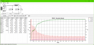
I actually have launched PSUD2 halfway writing the above. It first gave me a nice result, then I thought I'm missing a part of my supply filtering and effectively, by configuring it appropriately, brought back the problem.
All the input data I can have:
Transformer voltage : 300V AC
Winding resistance: 265Ω (one half - center tap to end)
Rectifier tube: AZ41 (close to AZ11)
Capacitor(s): 50uF/500V, measured 58uF, 0.8Ω ESR
Choke: Measured 9.8H, 216Ω
Load:
EL41, 36mA as stated in datasheet for standard application;
EBC41, 1mA same condition.
EL41 is specified for std. application under 250V, and the part values from original schematic are very close to that application definition (see my first post, where I added the schematic).
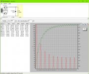
So with the PSUD2 configured even for slightly higher current (basically a worse case), I might get 385V DC, which is, unsettling I might say. Or, maybe I'm reading something wrong?
I suppose it could be good to somehow get the parameters of the output transformer and figure out what the author had in mind, because maybe he designed it for a bit higher voltage than in default application? But it sounds like an overkill to do..
Attaching the PSUD screenshot.
Looking forward to your reply and as always, many thanks for your invaluable help!
Jakub
And well, looking at that multimeter manual made me think I might need a better one. I might try to do some measurements at work later, where I have, supposedly, something better. This will wait of course, until I have the proper mains socket and wires on hand - 2 weeks, best case.
Meanwhile, I have been thinking on this troubling matter of power supply voltage and I think I'd use some help on this one. It will be very important later, when I will start building the initial output and preamp stages.
Step 1.
Assuming - I think we can - the AC output voltage from transformer is around 300V RMS AC.
Then, with ideal rectifier, we can estimate the rectified DC voltage by multiplying the AC value by 1.41, which gives us roughly 423V. We hardly have an ideal rectifier, so, I don't know, let's take a wild guess and substract something down to around 350V.
What I mean, is this is still too much for the output stage. If that was the case - what should I do?
I know that the supply voltage is supposed to sag when under load of several tubes connected, but for now I will have just two, at most.
Step 2.
I actually have launched PSUD2 halfway writing the above. It first gave me a nice result, then I thought I'm missing a part of my supply filtering and effectively, by configuring it appropriately, brought back the problem.
All the input data I can have:
Transformer voltage : 300V AC
Winding resistance: 265Ω (one half - center tap to end)
Rectifier tube: AZ41 (close to AZ11)
Capacitor(s): 50uF/500V, measured 58uF, 0.8Ω ESR
Choke: Measured 9.8H, 216Ω
Load:
EL41, 36mA as stated in datasheet for standard application;
EBC41, 1mA same condition.
EL41 is specified for std. application under 250V, and the part values from original schematic are very close to that application definition (see my first post, where I added the schematic).
So with the PSUD2 configured even for slightly higher current (basically a worse case), I might get 385V DC, which is, unsettling I might say. Or, maybe I'm reading something wrong?
I suppose it could be good to somehow get the parameters of the output transformer and figure out what the author had in mind, because maybe he designed it for a bit higher voltage than in default application? But it sounds like an overkill to do..
Attaching the PSUD screenshot.
Looking forward to your reply and as always, many thanks for your invaluable help!
Jakub
Attachments
Last edited:
The power transformer primary winding has a DCR that should be included - check PSUD2 help. The AZ11 has about 5V lower anode drop at 20mA than the AZ41, so there is a significant difference.
The idle plate-cathode voltage of the EL41 is less than B+ due to cathode bias, and OPT primary resistance. Max design rating for anode and screen is 300V, but that could be exceeded in some equipment for idle conditions.
The EL41 average screen current may increase significantly at max output, eg. from 1-2mA to 10mA, which would sag B+ a bit.
- Home
- Live Sound
- Instruments and Amps
- Converting old tube radio into guitar amplifier with few addons - help needed