Hello!
I am very new to tube amps, but am fairly well versed in the world of electronics, so I was hoping for a bit of help! For a while now I have been thinking about building a stand alone pre amp based on the Klemt Echolette NG51. If you've ever used one, you'll know how lovely this old german machine sounds! I decided to design the power section from scratch and being fairly new to the the world of tubes, I was hoping I could get some help verifying the schematic before I begin ordering parts/building it. Another important feature I wanted to include was the "magic eye" valve VU indicator. Below you'll find the schematics. Am I on the right track here?
Any and all help/input is greatly appreciated!
My Schematic (note, "A" is where I think the VU meter should go?):
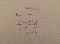
EM84 Valve VU Meter Circuit (not from schematic):
The Original Service Notes:
I am very new to tube amps, but am fairly well versed in the world of electronics, so I was hoping for a bit of help! For a while now I have been thinking about building a stand alone pre amp based on the Klemt Echolette NG51. If you've ever used one, you'll know how lovely this old german machine sounds! I decided to design the power section from scratch and being fairly new to the the world of tubes, I was hoping I could get some help verifying the schematic before I begin ordering parts/building it. Another important feature I wanted to include was the "magic eye" valve VU indicator. Below you'll find the schematics. Am I on the right track here?
Any and all help/input is greatly appreciated!
My Schematic (note, "A" is where I think the VU meter should go?):
An externally hosted image should be here but it was not working when we last tested it.
EM84 Valve VU Meter Circuit (not from schematic):
An externally hosted image should be here but it was not working when we last tested it.
The Original Service Notes:
An externally hosted image should be here but it was not working when we last tested it.
No links load.

PDF is better.
http://www.peel.dk/Dynacord/pdf/Echolette NG 51.pdf
http://www.peel.dk/Dynacord/pdf/Echolette S NG 51 (Manual).pdf
PDF is better.
http://www.peel.dk/Dynacord/pdf/Echolette NG 51.pdf
http://www.peel.dk/Dynacord/pdf/Echolette S NG 51 (Manual).pdf
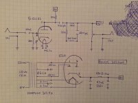
I think there are some issues with your schematic/plan:
1) The tone pot is missing its wiper (connects to ground).
2) The volume pot is missing its value (500K).
3) The stage uses grid current biasing and is meant for high impedance microphones (input signal: 5 to 200 mV). Unless you would use it with a microphone that gives of (close to) 200 mV, the output level of just this stage would not be high enough for the magic eye.
4) One diode shorts one half of the signal swing to ground, the other half over a 5M level pot to the grid of the magic eye. With just the 68K resistor (and the coupling capacitor) separating the output of the preamp to the diodes, I think this creates quite some distortion because the total load the ECC83 will see, varies a lot (in part of one half of the signal swing it sees a way lower load than the other half of the signal swing). The seperation should be way better anyway, so the 68K should be way higher (1M). But than the signal for driving the magic eye would get even lower...
5) The output impedance will be pretty high when the volume pot is at a high position. Unless you connect the preamp to the main amp with a very short cable, this can give high frequency roll-off and noise. Lowering the value of the volume pot will lower the maximum output impedance, but at the price of gain in the stage.
Addition:
6) Use a way higher value resistor than the 470 Ohm in the power supply (something like 33 K or even higher) and maybe add an aditional smoothing stage. Else you will have a lot of hum.
Last edited:
")
Ive found myself with some spare time, finally. I am going to pick this project up again and I thank you for the suggestions. After reevaluating what kind of undertaking I actually want to embark on, I am wondering if it would be reasonable to try to run this thing at pedal appropriate voltages. Im thinking 12vdc from a standard power supply, negating any of the need for the power section. I realize that the magic eye tube circuit will no longer work under these conditions. Im also thinking about trying a potentiometer to ground to set the grid bias of the tube. Otherwise, what modifications might I need to make to the circuit to be able to achieve this? Thanks!
Last edited:
- Status
- This old topic is closed. If you want to reopen this topic, contact a moderator using the "Report Post" button.
- Home
- Live Sound
- Instruments and Amps
- Klemt Echolette NG51 Valve Pre Amplifier