HI all.
I've recently pulled my old Guitar amp out of the garage only to find it's dead.
First observations were:
When turned on:
Latest Observations:
I'd love to get this thing working again. Any ideas as to what the problem is or where to look next?
(i am armed with a soldering iron and a multi-meter and an engineering degree)
Cheers,
Chris
I've recently pulled my old Guitar amp out of the garage only to find it's dead.
First observations were:
When turned on:
- No Lights,
- Slight speaker hum,
- speaker pops when turning off
Latest Observations:
- Power plug fuse in working order
- Measured continuity in both primary and secondary coils of transformer
- Cant see any obvious faults in soldering etc, circuitry
- If left on for a minute or two i can smell a slight burning smell - a lot like a hot glue gun smell
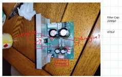
- From inspection it looks as if the two large(physically) resistors in the centre of the chip (see pic) are whats burning the glue around and on them. (i was able to measure an appropriate resistance across these resistors)
I'd love to get this thing working again. Any ideas as to what the problem is or where to look next?
(i am armed with a soldering iron and a multi-meter and an engineering degree)
Cheers,
Chris
If the speaker makes sound, it is working. Maybe not well, but working. The pop at turn off tells me the power amp is likely working. All that tells me the power transformer is probably fine - they usually are. I'd suspect your transformer puts out a simple supply for the power amp and step down zeners for the preamp. If you have a separate winding for low voltage rails, check it.
No lights makes me think a low voltage supply us gone -- like 15v for op amps or some such. Are both rails present at any op amps?
No lights makes me think a low voltage supply us gone -- like 15v for op amps or some such. Are both rails present at any op amps?
Agree and add: FULLY lacking any data about your amp, please upload at least a couple gut pictures showing:
* the power supply , large filter cap labels should be readable, diode rectifiers too.
* show the power amp, clearly visible chipamp if used, or power transistors, whatever´s attached to heatsink.
* preamp so we see whether it´s discrete of Op Amp based.
Since some labels will not be visible/readable, make a small list stating: chipamp / power transistors / filter caps / Op Amps so we can identify them and suggest "measure voltage on such and such pins"
We can and will guess a lot, but we need at least a *minimum* of data; so far we are absolutely blind.
Last edited:


Hi All
I've made some more measurements:
LM1875T
The low supply to the Pre-amp makes me think the fault lies before this stage.
The two physically larger resistors on the chip pictured get very hot very quickly when the power is on - could they or something adjacent to them be shorted/damaged?
I've made some more measurements:
LM1875T
Vcc -21V
Vee 21V
AC InVee 21V
0V
16.6V
33V
Supply to Pre-Amp16.6V
33V
-15V -> measured -6mV
gnd -> measured +9mV
+15V -> measured 24mV
gnd -> measured +9mV
+15V -> measured 24mV
The low supply to the Pre-amp makes me think the fault lies before this stage.
The two physically larger resistors on the chip pictured get very hot very quickly when the power is on - could they or something adjacent to them be shorted/damaged?
Attachments
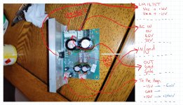
With boards reassembled on chassis and everything connected *except* the Red Blue Black cable (which I guess is the +/-15V supply from power board to preamp) turn amp on and measure as indicated, red probe to test points straight on resistor legs, black probe on supply ground or chassis ("should" be same thing) you "should" measure the voltages I suggest.
Post results.
Post results.
Attachments
I no longer think the problem lies on that board.
I realised the measurements i was making for the -+ voltage supplies would only give the desired -+15V when an appropriate load was applied at the other end of the supply (i.e. the pre-amp circuit board)
When i measure the outputs of the connected 15V supply i get approximately 100mv across the whole thing. (similar voltages regardless of which channel is on)
The resistance between the supply pins of the pre-amp board is very large when measured while disconnected which explains why the voltage supply was so low when connected.
So somewhere on the pre-amp board there must be something contributing to this? Not sure what the culprit could be.
Why?I no longer think the problem lies on that board.
Definitely NOI realised the measurements i was making for the -+ voltage supplies would only give the desired -+15V when an appropriate load was applied at the other end of the supply (i.e. the pre-amp circuit board)
Did you MEASURE what I WASTED time suggesting on post# 4?When i measure the outputs of the connected 15V supply i get approximately 100mv across the whole thing. (similar voltages regardless of which channel is on)
Including downloading, editing and uploading the picture?

Who asked you to do that?The resistance between the supply pins of the pre-amp board is very large when measured while disconnected which explains why the voltage supply was so low when connected.
Measure VOLTAGE.
Please do the suggested tests.So somewhere on the pre-amp board there must be something contributing to this? Not sure what the culprit could be.
- Status
- This old topic is closed. If you want to reopen this topic, contact a moderator using the "Report Post" button.
- Home
- Live Sound
- Instruments and Amps
- Ibanez TBX15R - Broken