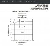
Not the capacitance on the rails -- the total capacitance on the TLE Output pin. The part has a region of instability that I don't think we're anywhere near, but it does occur as a slight possibility. (see below)
The resistor splitter doesn't constitute a high impedance power source; but the series resistor we've fitted in the B+ line for current limiting during testing does.
There is more measuring and checking we can do before we tear up the board too much with unsoldering and design revisions.
e.g. Do we know yet whether it passes signal? It may be unstable if the tone pots are not connected.
Attachments
I'm not sure how to calculate thisNot the capacitance on the rails -- the total capacitance on the TLE Output pin.
Oh ok, so for testing i didn't include the resistor in series with the power suply, just straight to battery and amp-meter in series to get the current drawThe part has a region of instability that I don't think we're anywhere near, but it does occur as a slight possibility. (see below)
The resistor splitter doesn't constitute a high impedance power source; but the series resistor we've fitted in the B+ line for current limiting during testing does.
Ok, just let me know what. If an osciloscope is needed i'd need to buy one and probably wait a month or so for deliveryThere is more measuring and checking we can do before we tear up the board too much with unsoldering and design revisions.
Oh yes, i ran a signal through it and sound wise it performs very nice, no noise or anything weird, the tone control works very well both boost and cut all the way... i also think now the RF is gone, haven't tested that specifically cause it's unaudible with signal running. So yeah, sound wise i'd say it's how it should sound, no audible issues. I let it run for half an hour or more and worked great in that regard.e.g. Do we know yet whether it passes signal? It may be unstable if the tone pots are not connected.
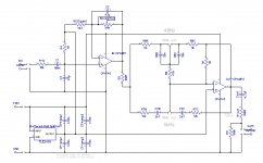
Here's what i have in the circuit right now:
Attachments
This will take some study. May still need a 10 or 22 uF cap at the battery terminals (I know  -- after I told you to omit it ..).
But let's take some time with a simulator before we hack up your pretty board.
Maybe I'm just being deceived by the tiny size of it, but are the holes for connecting wires large enough to poke a capacitor lead through with the battery lead?
-- after I told you to omit it ..).But let's take some time with a simulator before we hack up your pretty board.
Maybe I'm just being deceived by the tiny size of it, but are the holes for connecting wires large enough to poke a capacitor lead through with the battery lead?
WellThis will take some study. May still need a 10 or 22 uF cap at the battery terminals (I know
But let's take some time with a simulator before we hack up your pretty board.
Maybe I'm just being deceived by the tiny size of it, but are the holes for connecting wires large enough to poke a capacitor lead through with the battery lead?
just tried this at 18V, aaand 10uF brings down consumption to about 2.8mA, and 22uF brings it down to about 1.16mA. Tried 100uF just to see and it's the same as 22uF.Is this the oscillation you were talking about related to not having a power cap or it's something else?
Also, why is this not the case with the 43k resistors? And they still consume slightly less than the TLE, about 1.1mA compared to 1.16mA for th TLE. Is it better at the end to just use resistors or what? It baffles me.
The holes are exactly as the wire, 0.8mm. Looks like we need to insert 22uF power cap and will have to go on top of the pins and lay it down on top of other components.
> Is it better at the end to just use resistors or what?
No, just keep tarting it up until nobody has any idea what it is doing.
_I_ think returning RG2 to the half-supply point is a fallacy. This is not a DC amplifier, DC point, DC feed--- it sets AC gain. It therefore can return through its own capacitor. Much less liable to troubles than returning to a node shared with amny stages both AC and DC.
When you do that, the remaining loads on Vref are a couple opamp input pins, almost zero current. 100k divider will tie them up, using 2uA.
Attachments

Yes. That is exactly the behavior we would expect for an unintended oscillation.Is this the oscillation you were talking about ..
I wasn't sure that would do it. (Still haven't read every last word of the TLE PDF.)
- The resistors don't have gain.Also, why is this not the case with the 43k resistors? And they still consume slightly less than the TLE, about 1.1mA compared to 1.16mA for th TLE. Is it better at the end to just use resistors or what? It baffles me.
- That 60 microamps will vanish in obscurity once a guitar cord is being driven.
- No. The TLE is massively stiffer. A solid virtual ground is essential for acceptable performance.
So .. good on you! Glad you had the 3 values on hand to try. Much faster than tedious simulations. And you've proven exactly what it needs!
edit: But I like PRR's point, too. But it might want a diode or two for power-cycling thumps and he's trying to keep down both part size and counts.
Last edited:
My arithmetic comes out to 180 uA for 100k/18V, though the resistance could be doubled or more since these are JFET inputs. Just at the expense (part size: the single 4.7uF output cap already dwarfs everything else on the board) of needing a somewhat higher capacitance.
Then there's the audiophile 'capacitor sound' issue ..
Also, remember how many solid ideas to implement true ground w/+/-9V were dispatched due to complexity/parts count.
Cheers
) of needing a somewhat higher capacitance.Then there's the audiophile 'capacitor sound' issue ..
Also, remember how many solid ideas to implement true ground w/+/-9V were dispatched due to complexity/parts count.
Cheers
Thanks for all the explanation in the previous post Rick. It's good all had all the values on hand to try immediately and confirm what's enough.My arithmetic comes out to 180 uA for 100k/18V, though the resistance could be doubled or more since these are JFET inputs. Just at the expense (part size: the single 4.7uF output cap already dwarfs everything else on the board
Then there's the audiophile 'capacitor sound' issue ..
Also, remember how many solid ideas to implement true ground w/+/-9V were dispatched due to complexity/parts count.
Cheers
PRR's mod may be a good solution too, but it requires 3 additional electrolytic caps, I'm struggling to fit one more on the pcb now, the final version is even smaller, I made it 23x23mm due to the encapsulating housing I found to be at 25x25mm externally and internals are barely 23x23mm. So even one more electrolytic cap is a big challenge. I may try that mod if I redesign the pcb and go larger.
The output electrolytic is big due to the high ripple current, I think this one is 1060mA. It was suggested to use electrolytics for audio with as high ripple as possible so there it is. The power cap will be big cause of the same plus larger capacity. So if the resistor solution would require that many caps it would be close to impossible to place that many components of that size on that pcb. And since I already have a good pcb I guess at this point would be best to just find a way to place the power cap somehow on top.
All the components are audio grade of some sort, probably not audiophile grade, those are just physically enormous and not for on board usage. I'm happy with the current sound, noise level, performance etc it's pretty good. We have really good opamps here with FET inputs too. Sound wise I wouldn't change anything.
For the current draw, calculations are about 0.9-0.95mA for both opamps and 0.17 for the TLE which sums up to 1.12. There is only 40 micro amps more to 1.16mA which are probably due to the rest of the components. Overall seems reasonable and on point current draw.
I very appreciate the help of all who contributed and wanted to help, special mentions JMFahey, PRR and Rick, you helped the most. From component type suggestion thread we ended up redisigning the circuit and it turned damn good.
Yes-sir-ee Bob (pardon the colloquial ) -- anything that affects stability, physical position matters. Maybe before your next project, you could plan on acquiring an inexpensive 'scope so you could properly pursue such gremlins ..? The market is thick with analog 'scopes being retired -- there should be some good prices.
Meanwhile, give yourself a big pat on the back for a job well done! The current draw is dead on; measuring 10's of microamps merits a little wider tolerance as well as lower expectations. And remember, it'll draw more current driving a cable.
Best of all, it sounds like you're happy with it! Congrats!
Best Regards
) -- anything that affects stability, physical position matters. Maybe before your next project, you could plan on acquiring an inexpensive 'scope so you could properly pursue such gremlins ..? The market is thick with analog 'scopes being retired -- there should be some good prices.Meanwhile, give yourself a big pat on the back for a job well done!
The current draw is dead on; measuring 10's of microamps merits a little wider tolerance as well as lower expectations. And remember, it'll draw more current driving a cable.Best of all, it sounds like you're happy with it! Congrats!
Best Regards
Yes-sir-ee Bob (pardon the colloquial
Meanwhile, give yourself a big pat on the back for a job well done!
Best of all, it sounds like you're happy with it! Congrats!
Best Regards
Haha, like your spirit. If I decide to build more, a small scope seems like a good move. There are some new digital ones that are a fraction of the size of the analog, may check those out too.
Yup, I'll test even on longer cables to see the difference.
Well thanks to you Rick and the rest of the guys again
Not necessarilyI already have the PCB made without those resistors so modifying it would involve making a new one.
Almost always you can cut the relevant track , drill two 0.45 to 0.8mm holes one on each side simply for mechanical strength, pass resistor leads through them and bend them so they can be tack soldered to existing pads at track ends.
Or scratch 5 or 6 mm solder mask over each track stub to solder component leads.
mechanically weak but through holes avoid resistor vibrating and tearing thin tracks off.
Done it 1000 times with success.
Well I can do that but I'll damage nice factory pcb. Even though that's the second problem, the first is that that mod requires 4 electrolytic caps on a 23x23mm pcb. There's not enough room for that many on this pcb.
I'm don't have a problem even redoing the pcb but keeping it this small is preventing me from adding any more electrolityc caps. Besides that I got this one working very nicely with on point current draw - exactly as the datasheets say for the active components and it sounds really good.
But I'll definitely try that mod if I'm about to build this as a pedal without space restrictions cause I'm thinking of that too at some point and making direct access to some tweak points
- Status
- This old topic is closed. If you want to reopen this topic, contact a moderator using the "Report Post" button.
- Home
- Live Sound
- Instruments and Amps
- Component suggestion for a preamp please