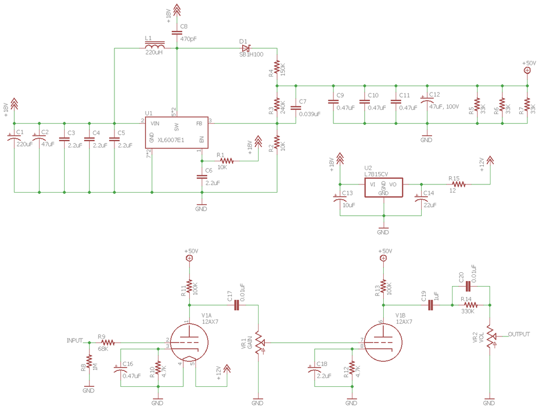
Joyo BantAmp 12AX7 Tube 18V DC Power Supply Schematic
So the Bantamp amps by Joyo only run 50V on the tube. We can get +/- 24V boost supplies from China for a couple of bucks.
So the Bantamp amps by Joyo only run 50V on the tube. We can get +/- 24V boost supplies from China for a couple of bucks.
A number of years ago, there was a guy playing around with 12V Guitar tube amps. I built one - it sounds pretty good (but has very little headroom before distortion comes in).
The web site is dead now - but I found it on the Wayback machine (hopefully this link will work):
Sopht amps - all tube 12v amps
Pretty easy to build and kind of fun...
Rich
The web site is dead now - but I found it on the Wayback machine (hopefully this link will work):
Sopht amps - all tube 12v amps
Pretty easy to build and kind of fun...
Rich
A number of years ago, there was a guy playing around with 12V Guitar tube amps. I built one - it sounds pretty good (but has very little headroom before distortion comes in).
The web site is dead now - but I found it on the Wayback machine (hopefully this link will work):
Sopht amps - all tube 12v amps
Pretty easy to build and kind of fun...
Rich
Not much power from them.
A good oldie tube is the 12A6, runs off of 12V and only 0.15A heater current. 3.4W 250V, 40mA 8k ohm OT looks about right. Would be my choice on battery power.
http://www.r-type.org/pdfs/12a6.pdf
A good oldie tube is the 12A6, runs off of 12V and only 0.15A heater current.
I played with those 10+ years ago. I had a heathkit amp that used them which I sold, and I gave him my bag full of 12A6's with the amp.
I could get almost 5 watts from a pair of 6AK6's for the same heater power on about 200 volts. There is still a breadboard 6AK5 - 6AQ6 driving P-P 6AK6's amp that I did for the HBAC in a box here somewhere.
I went off on a tangent using pencil tubes driving 6AK6's trying to make a tube amp that fit inside an electric guitar. There was a simple boost converter that ran everything from a 11.1 volt LIPO battery from a model helicopter. Amp worked, speaker didn't (sounded ugly).
Surely there isn't really a 150k resistor in series with the 50-volt B+ rail?
I'm guessing the B+ rail actually connects to the right end of the diode?
Every guitar device I've ever tried with a low power supply voltage seems to have the same problem mpeg2 mentioned - there's very little headroom before distortion comes in.
-Gnobuddy
Attachments
Many old tube amps have rather small filter caps which are also, well....old. They might work fine when plugged into clean wall power, but may buzz like crazy when fed the "modified sine wave" that these small inverters make. It's really a square wave with some dead time so that the total heat energy is similar to a sine wave. It contains LOTS of nasty harmonics well into the audio range.
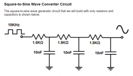
Do you think the modified sine wave could be cleaned up by some circuitry? The attached is a base schematic for something I was playing with, it converts a square wave coming from of a 555 timer at 6V 10Khz to a sine wave and it creates a very good sine wave. You would have to play with the values of the components. For me it did however cut the output voltage considerably in simulation. I actually modified it to run at 1Mhz. The question is can such a circuit really work on 120VAC 60Hz modified sine wave, under the load of the tube amp and if so what would the output voltage be? I was only looking at it for use as a sine wave oscillator. You could always build your own inverter instead. Battery --> regulator circuit --> oscillator --> Step up Transformer.
Attachments
Last edited:
That's the catch! Each of those big series resistors would eat up a lot of the available power, and drop a lot of the available voltage, so you wouldn't get much at the output of the filter....it did however cut the output voltage considerably in simulation...
As long as there is no attempt to draw any significant current out of the filter, it will work for the purpose it was originally designed for - to filter out most of the harmonics from a square wave signal generator, leaving something close to a sine wave.
Using an external AC inverter sounds attractive because it's such a simple approach - you can just plug in any AC-operated guitar amp you already have - but even if you find the right pure sine-wave inverter, it's an inefficient approach, because of all the power conversions back and forth. That means reduced run-time on battery operation.
The approach suggested by Printer2, Fenris, and Tubelab - using a high-voltage boost converter running on the battery to provide the B+ for the valves - is more complicated and requires more DIY, but it will use the limited amount of stored energy in the battery more efficiently, and run the amp longer at the same power output.
I'd never heard of the Joyo Bantamps before. I was impressed by some of the sounds they produced in online video reviews. Ditto for the Orange Micro Terror, which also uses the recipe of a class D power amp, a single 12AX7 in the preamp, and analogue solid-state bits before and after the tube.
It seems the Bantamps use an 18V power supply, while the Micro Terror uses a 15 volt one. If a Bantamp or Micro Terror will run straight off the 12V car battery instead, that might be the simplest solution for the OP. All you'd have to do is add is a small speaker cab to take on the trip with you.
-Gnobuddy
You would have issues trying to install a filter like this on the AC line voltage input to the existing amp for two reasons. The currents involved would require rather small resistor values. This puts a good deal of capacitance on the output of the inverter, which may not like it.
The inverters in question take 12 volts and boost it up into the 160 volt range with 2 mosfets and a transformer, then rectify it into 160 volts of DC. The DC is then chopped up into a "modified AC sine wave" with a 4 mosfet H bridge. The "chopper" circuit needs fast rise and fall times (guaranteeing lots of harmonics) to get by with minimal, or no heatsinking. Adding a capacitive load to these things usually makes smoke, melted fets, or just instant deadness.
So what does the Dumm Blond do after he smokes an inverter? He cuts out the dead fets, and taps the raw 160 VDC supply to run the tube amp B+, done! You can get over 300 volts from a European spec 240 volt inverter.
A filter like you show could be used to clean up the DC supply inside the amp, but the OP has an existing vintage amp that he is probably not going to experiment on. It has been my experience that once that nasty waveform gets near the amp, you can't clean it up. I have been using a 700 watt inverter and a boat battery for outdoor sales and such and I find that it will put out a strong enough buzz that it can be picked up on an AM transistor radio from 50 feet away.
The now common inverter generators are almost as bad, at least mine is. I haven't met a guitar amp, tube or solid state that doesn't have an audible buzz when plugged into that thing. Keep it 50 feet away on an extension cord and it's tolerable.
Surely there isn't really a 150k resistor in series with the 50-volt B+ rail?
I'm guessing the B+ rail actually connects to the right end of the diode?
Every guitar device I've ever tried with a low power supply voltage seems to have the same problem mpeg2 mentioned - there's very little headroom before distortion comes in.
-Gnobuddy
The poster took the values off the board, could be a typo or read the value wrong. I would not use it anyway, was more interested in the tube section. Those Bantamp amps sounded good enough to me that I was curious about how they designed their amp. I found a RF test report online, posted the link in another forum.
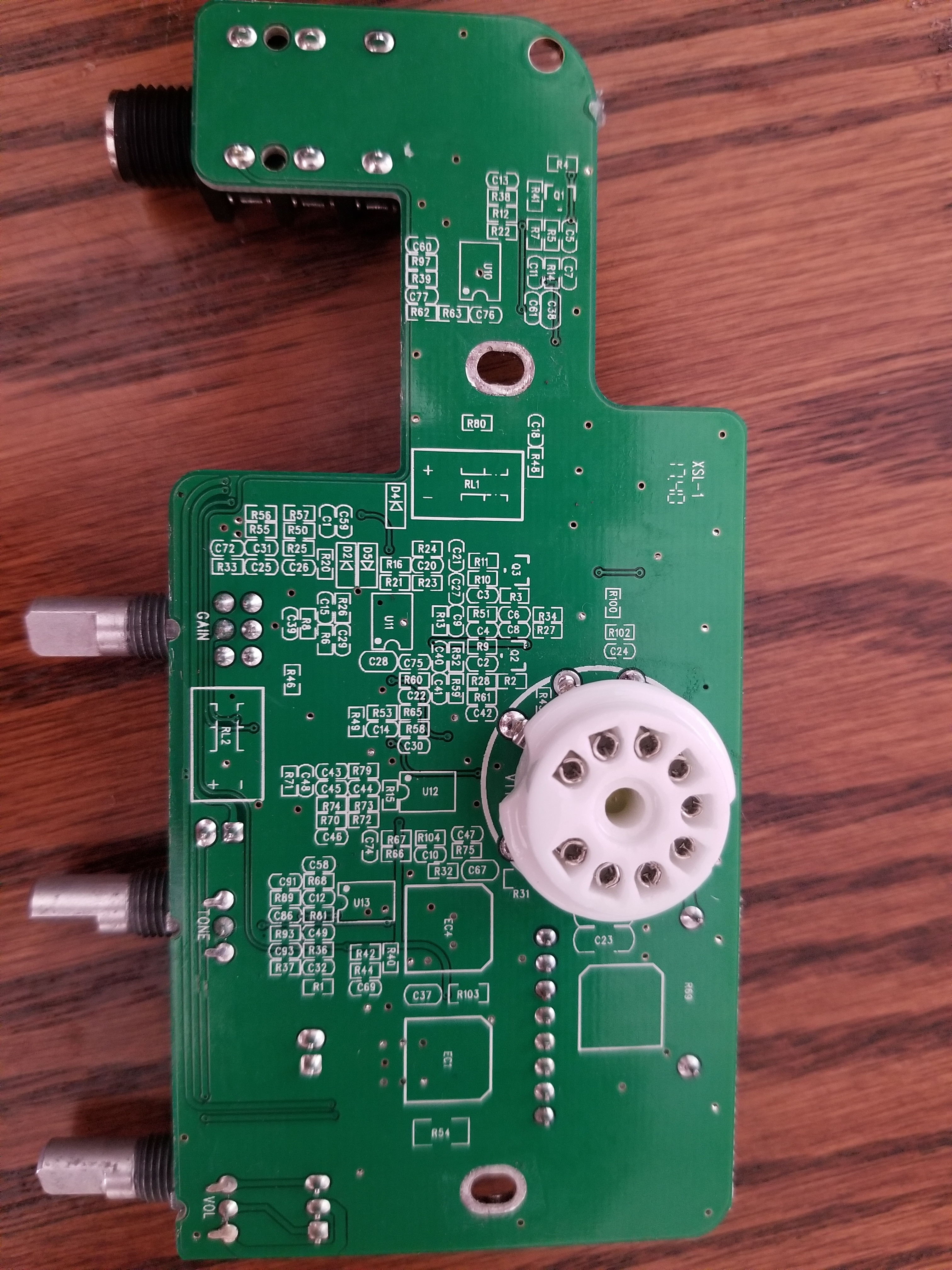
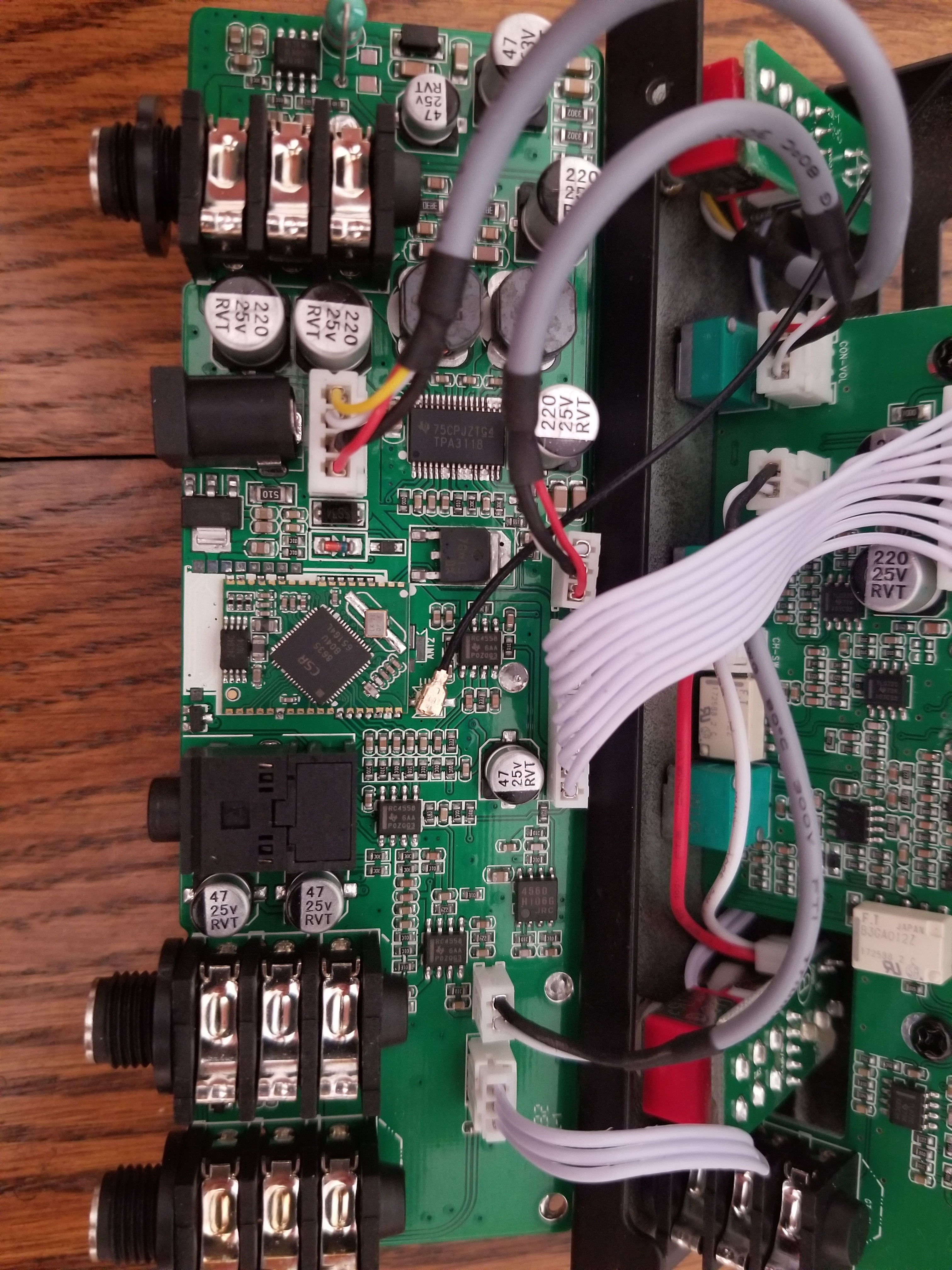
BANTAMP MINI TUBE GUITAR AMPLIFIER Teardown Internal Photos ANNEX_Part 15C JOYO TECHNOLOGY
Nice find!Those Bantamp amps sounded good enough to me that I was curious about how they designed their amp.
The square chip with the forest of legs - I wonder if that's a DSP chip? And if so, I wonder how much of the Bantamp's magic is worked in DSP, and how much from the actual 12AX7? Tube emulation, or just voicing and tone controls and whatnot?
The sounds in this old 2012 review ( YouTube ) of a Micro Terror surprised me, as being better than I was expecting to hear. It seems to be another little amp that follows the same basic recipe as those Joyo Bantamps, with an analogue solid-state preamp, a 12AX7, and a class-D output section.
-Gnobuddy
DSP, if I remember correctly the amp might have Bluetooth. What I am guessing at is that rather than getting each amp in the series re-certified they do the one and then just put in for the different input board, which has an 8-pin IC and the tube socket on it. It seems the schematic and the photos are different, the schematic having a single 100V filter cap and the photo having two 220 uF 25V that I guess they stacked. So is the IC used as a way of generating the 50V or is it an opamp? I can not see the inductor needed if it was generated there. But then why have the capacitors there? Looks like the pots may be sampled remotely due to the connectors for each of them. As you wonder, is the sound coming from the DSP chip? Hard to say.
Looking at the other board, they have another couple of 220 uF 25V caps, so maybe for the opamps? They do have a 63V cap and inductors so maybe the voltage boost is done on the main board.
Looking at the other board, they have another couple of 220 uF 25V caps, so maybe for the opamps? They do have a 63V cap and inductors so maybe the voltage boost is done on the main board.
Last edited:
Further on the Joyo.
their circuits are generally -> op-amp the signal -> feed into 12AX7 tube -> do some tone shaping -> go into solid state power amp, which in the case of the Zombie is a TPA3118. So, how are they getting the voltages to drive a 12AX7? A nice SOIC-8 boost chip: XL6007E1.
Quote
Does the rest of the circuit have any other hard clipping elements in it?From just the pure elements of the power supply setup, no. But there did appear to be a set of diodes in there, but without really going into it hard, I couldn't tell if it were hard clipping of soft clipping. There appeared to be several TL072 surface mount opamps, and the diodes were close to them.
Actually, I noticed a flub in my schematic and made me a JLCPCB version of, so I know it works now. Here is the corrected schematic

I drew the 50V rail on the wrong part. This schematic has it corrected and I built a PCB to verify it.

https://www.diystompboxes.com/smfforum/index.php?topic=124100.0
Thanks for the update!Further on the Joyo.
I'm still curious about the large square chip with leads on all four sides. At first sight, there is no obvious reason for this little amplifier to have digital processing inside - there's no LCD display or other external evidence of digital technology. So, as we guessed earlier, this chip is most probably a DSP rather than a general-purpose microcontroller.
If that's the case, there's no need to do such crude things as using diodes to clip the guitar signal, when you can do much better-sounding and more subtle things in DSP instead.
I found a couple of these on sale in Canada now for about $200 CAD. They're practically giving them away. I can see the appeal, especially for busking or backyard noodling or something like that.
-Gnobuddy
> curious about the large square chip
CSR8635 | Qualcomm
CSR8635™ Development Kit - Qualcomm | DigiKey Electronics
CSR8635B04-IQQF-R Qualcomm | RF/IF and RFID | DigiKey
The chip does "everything" and costs $2 if you buy a full box.
CSR8635 | Qualcomm
CSR8635™ Development Kit - Qualcomm | DigiKey Electronics
CSR8635B04-IQQF-R Qualcomm | RF/IF and RFID | DigiKey
The chip does "everything" and costs $2 if you buy a full box.
- Status
- This old topic is closed. If you want to reopen this topic, contact a moderator using the "Report Post" button.
- Home
- Live Sound
- Instruments and Amps
- 12V DC tube amp