Hello!
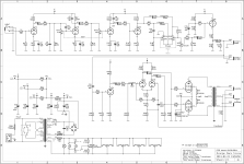
A friend of mine requested me to realise a Mojotone NC3015 for him, but im stuck with the question of what power and output transformer to use.
Here (Central Europe, Hungary) we have some available, made by Indel, after searching the net for clues, I saw that maybe an Indel TGL20/002 could be used for the output.
Is my assumption right?
He wants to stick with the tube rectification, I reckon that separate heater voltages should be used for the EL84s, the ECC83s and the EZ81 too. The Indel TSL100/001 seems the closest I can find here with 2x260V, 1x6,3V, 2x3,15V and 1x5V, altough the EZ81 also requires 6,3V heating as I see.
I can not find any info on how much is the anode supply on the original trafo used, I have a feeling that this is much higher than what originally needed. Is there a way to modify the circuit to fit these two transformers into it?
All of your help is appreciated, thanks in advance!
Attachments
> I reckon that separate heater voltages should be used for the EL84s, the ECC83s and the EZ81 too.
Why? These all eat the same heater voltage.
As far as power, this is a "Marshall 18 Watt" for practical purpose. The preamp details are different but that does not change the power reckoning. Are "Marshall 18W replacement" transformers available in your shops? (They are generic here.)
Why? These all eat the same heater voltage.
As far as power, this is a "Marshall 18 Watt" for practical purpose. The preamp details are different but that does not change the power reckoning. Are "Marshall 18W replacement" transformers available in your shops? (They are generic here.)
As what I read on the topic, it is fortunate to use seperate supplies if possible because of noise reasons. I dont know how much of it is true for guitar amps, but I think it can not hurt.
I looked around well, there are no third party trafos available here other than those Indel ones. Maybe I could order in Hammonds, but that defeats the goal of be as cheap and easily sourced as possible. (Same goes for the original kit.)
I looked on what hammond suggests for 18W marshall combos, for power its the 290PAZ with 290-0-290V 140mA, 6.3V 2A outputs. Thats only a bit beefier on the HT side than what I chosen.
For output its the 1750PA, with a 8,4k primary and 0-4-8-16 secondary, it has 70-15kHz range.
The Indel sadly does not have an as well detailed datasheet as the Hammond and I have to give up on the secondary taps, but that clearly has a bigger core size, they say a 30-15kHz range on it. Altough it has a primary impedance of 10k.
Question is if the bigger core size will change the tone noticeably (except the better response on low freqs) and if the change in the primary impedance will influence the operation of the output tubes significantly.
I would be happy if I could get away with these trafos without recalculating the whole circuit or importing hard to get parts. As I am too lazy to do that (it would surely put my EE degree to good use, but I was never too familiar with analog circuitries) and hopeless to rely on anybody doing that for me only for a simple thank you.
The fun part would be in building and boxing a proven curcuit, not the (re)design stuff.
Keep in mind that while you have an EE, most people messing with tubes today do not. There is a lot of nonsense floating around the Internet, so be prepared to discount most of what you read, unless you're sure it comes from a person who actually knows what he/she is talking about.As what I read on the topic...
Looking at it logically: heaters are not in the signal path. Their only function is to heat the cathode until it emits electrons. There is also a huge thermal time constant involved - the mass and bulk of the cathode averages out quick fluctuations in heater temperature, which is why it is possible to run the heaters on 60 Hz (or 50 Hz) AC. Normal levels of noise on the heater power supply simply do not couple into the actual signal.
So there is no good reason for using separate power sources for each heater. If someone claims otherwise, most probably it is just one more example of the superstitious nonsense that fills online discussions of tube circuitry.
The guitar itself only goes down to 83 Hz in standard tuning, and the guitar speaker rarely goes below 100 Hz, so both transformers will sound the same. 30 Hz is completely unnecessary for guitar, but won't hurt anything....Hammond...output...8,4k primary...70-15kHz range.
<snip>
...Indel...bigger core size...30-15kHz...10k.
There is only 16% difference between 8.4k and 10k. This is too small to matter. The tubes will have +/- 20% manufacturing tolerances already - so the 10k transformer might be a better match for the particular tubes you happen to use, who knows!
If you're really worried about the 10k versus 8.4k, simply wire a 51 ohm power resistor in parallel with your 8 ohm speaker; the transformer primary will now be 8.4k!
The 51 ohm resistor will need to be able to dissipate one-sixth of the amps power output, i.e. about 3 watts in the case of an 18-watt Marshall. I would recommend using a 51 ohm, 10-watt power resistor, so that the resistor remains safely within its power ratings with a wide safety margin.
(Trust me, though, this additional resistor simply will not matter. 10k or 8.4k is equally good as far as your output tubes are concerned.)
For clean tone, there will be negligible if any change in tone, because 70 Hz is already more than enough; the guitar doesn't go below 83 Hz in standard tuning.question...bigger core size...change the tone noticeably
If you overdrive the amp heavily, it does generate *subharmonics* of the original frequency, and these could be below 70 Hz. It is possible that the bigger transformer might make these subharmonics more audible. Bigger transformers might give your amp more "growl", if you have guitar speakers that can actually reproduce those lower frequencies.
I agree with Printer2, you won't have any problem using the stock circuit with these Indel transformers....if I could get away with these trafos...
Please post some build details and photos if you can, as your project proceeds!
-Gnobuddy
First, I would like to thank you guys for the replies!
Gnobuddy got my biggest problem right, it is hard to gain any selfconfidence in the topic, there are many opinions regarding every aspect of it, especially the hum/noise and OPT part. Its a small country, forums are mostly about hi-fi applications, full with BS and nonsense (atleast for the average user, who does not want a dead silent, minimalist high-end setup).
I will proceed with the parts list and start getting it together. I plan on using solder terminal boards and parts from my pile of exotic 30-40+ years old NOS or used parts. It will be set in a gutted Marshall MG100FX heads box.
I am sure you will hear about the project, atleast about parts layout and stuff like that.
I have an other device, a DIY mystery box i bought, 2xECC83, EL84, germanium or selenium rectification on HT. Its clear that it was a SE mixing amp, but I screwed up when drawing it back. Let me gather the pics and the drawing, will open a new topic for it. Im sure it will be interesting for you guys and maybe you can help me out with the drawing. (Tried it here in the local forums, they said its not right. No sht Sherlock! thats what i stated in the first sentence )
)
Gnobuddy got my biggest problem right, it is hard to gain any selfconfidence in the topic, there are many opinions regarding every aspect of it, especially the hum/noise and OPT part. Its a small country, forums are mostly about hi-fi applications, full with BS and nonsense (atleast for the average user, who does not want a dead silent, minimalist high-end setup).
I will proceed with the parts list and start getting it together. I plan on using solder terminal boards and parts from my pile of exotic 30-40+ years old NOS or used parts. It will be set in a gutted Marshall MG100FX heads box.
I am sure you will hear about the project, atleast about parts layout and stuff like that.
I have an other device, a DIY mystery box i bought, 2xECC83, EL84, germanium or selenium rectification on HT. Its clear that it was a SE mixing amp, but I screwed up when drawing it back. Let me gather the pics and the drawing, will open a new topic for it. Im sure it will be interesting for you guys and maybe you can help me out with the drawing. (Tried it here in the local forums, they said its not right. No sht Sherlock! thats what i stated in the first sentence
)You're very welcome!First, I would like to thank you guys for the replies!
I'll add one more opinion, but this one is based on reality (physics). If a person wants low noise, he/she should be using transistors or JFETs, not tubes. Both BJTs and JFETS are inherently less noisy than any tube!...many opinions...especially...hum/noise...average user...does not want a dead silent, minimalist high-end setup...
This is because RMS thermal noise (aka Johnson-Nyquist noise) is proportional to the square root of absolute temperature. A semiconductor device operating at about 300 Kelvin (room temperature) therefore has an automatic factor-of-two advantage compared to a tube with its cathode heated to about 1300 Kelvin (~1000 Celsius, a typical cathode temperature for receiving tubes of the sort we use for audio.)
If you want even lower noise than you can get from one well-chosen BJT or JFET, then you can use an IC that puts hundreds of pairs of BJTs in parallel, statistically reducing noise by the square root of the number of devices in parallel (uncorrelated noise currents add as the square root of the sum of squares, while correlated signal currents add linearly, so the S/N ratio goes up as the square root of the number of devices in parallel.)
And if you want even less noise than that, you have to go in exactly the opposite direction to a tube: instead of a heated cathode or room-temperature semiconductors, you have to cool down your semiconductors with liquid nitrogen, like the big boys do.
Having disposed of low-noise-tube nonsense, now let's talk hum.
Logically, AC heater operation in an audio amplifier is a terrible idea. The commonly used AC power frequencies (50 or 60 Hz) are in the audio band. Running wires carrying large currents - amperes - at audio frequencies, through the guts of a high-gain audio amplifier, is an absolutely idiotic idea, a recipe for injecting huge amounts of annoying hum into your signal. No sane audio engineer would ever choose to do this if she thought about it for even a moment.
But back in 1945 or so, there was no way to turn AC mains power into amperes of clean DC. So your options were to power the heater with AC, or power the heater with batteries. In houses with no AC electricity, batteries were actually used, but the steep cost and short life was a big problem. If the house did have AC power, then using AC for the heaters was the lesser of the two evils, so AC heater power had to be used, terrible though it was. There was no third choice.
Since there was no better choice, engineers of the time had to tolerate the severe failings of AC heater power, and develop the best work-arounds they could. So the art of twisting heater wires, running them close to chassis metal, et cetera, was developed. These were ways to make the best of a bad job.
Fast-forward to 2020. Today we have cheap, reliable switch-mode power supplies that can easily produce a few amperes of clean, hum-free DC. What little noise remains is above the audio frequency band, and is very easy to filter out with a small RC network, because the frequency is so high.
In other words, the best heater power for a tube amp in 2020 is not any kind of AC - it's a cheap modern SMPS!
But in 2020, most tube Hi-Fi people are not into engineering. They seem to be into a weird kind of religion instead, one where you worship the past, worship antique technology, and most especially, worship glowing glass bulbs. The most holy of all glowing glass tubes seem to be, for reasons I don't even want to think too much about, very expensive ones manufactured in Germany during the Nazi era.
At any rate, for people with that mindset, using an SMPS on their precious holy tube is sacrilege, like shoveling manure into a church. So they continue to prefer and use the solution that was used in 1945, even though it's a very poor choice today. Or they make ridiculous huge, expensive, heavy, fan-cooled linear regulated power supplies dissipating tens of watts. I'm not sure why linear regulators are sufficiently holy to use with tubes, but SMPS are not!
To make my position clear, I do like tube amplifiers - for use with electric guitars, not for Hi-Fi. I don't pretend that they are low-noise by modern standards, and I certainly don't pretend that they are Hi-Fi. I like them for use with guitar because the inherent flaws of vacuum tubes happen to complement the inherent flaws of electric guitars, so that the two of them together sound better than either one by itself.
-Gnobuddy
This is because RMS thermal noise (aka Johnson-Nyquist noise) is proportional to the square root of absolute temperature. A semiconductor device operating at about 300 Kelvin (room temperature) therefore has an automatic factor-of-two advantage
That 3db is most useful when you're designing moving coil preamps for uVolt signals.
There's an old but still valid analysis, in Eric Barbour's article
The Cool Sound of Tubes
IEEE Spectrum ( Volume: 35 , Issue: 8 , Aug. 1998) pgs 24 - 35 DOI:
10.1109/6.708439
There's a side bar that compares linearity to noise floor with the conclusion that, in terms of available signal to noise, tubes still won (in their happy hunting ground).
Dig into the technical bits at your leisure. It's pretty light and easy to digest.
In short a) good triodes are still are the most linear devices ever made and b) transistor circuits are orders of magnitude cheaper, cooler and smaller. If you've got a budget to meet, transistors win every time.
The c) is that pentodes are still the best analog multipliers, but DSPs ate that cake a few decades back. With digital you can fake just about anything.
The real issue is that most line level amps (and this includes those with consumer grade supplies of any architecture) have way more noise on the power rails than in the amp.
And those built with conventional architectures (high feedback differential amps in AB) have no way of getting rid of that noise (especially when it's intermodulated by power rail sag). Doesn't matter whether the devices are vacume or bandgap.
Regarding budget reasons I would like to build this with russian tubes. As far as I got reading here and there, I reckon that 6P14P is a drop in replacement for EL84, and 6N2P can be use instead of ECC83s, if I modify the heater circuit for the correct pinout (or use a socket converter); am I right?
Do I have to watch out for anything else, biasing etc... ?
Do I have to watch out for anything else, biasing etc... ?
I have read that, but have no personal experience with either EL84 or 6P14P.I reckon that 6P14P is a drop in replacement for EL84,
...6N2P can be use instead of ECC83s...Do I have to watch out for anything else, biasing etc... ?
Pin 9 of the 6N2P should be grounded. It's an internal electrostatic shield between the two separate triodes.
Maximum voltage ratings for the 6N2P may be less than for vintage North American 12AX7s. Maybe don't use the 6N2P in any extremely high-B+ circuits.
-Gnobuddy
hordri,
did you buy the transformers you mentioned in #1 yet? If so, feed the small signal tubes from the 3.15-0-3.15 Vac winding and both EL84's and the EZ81 from the same 6.3 Vac winding. Ground one end of this winding. The EZ81 is designed to be operated like that and can cope with cathode to heater voltages up to 500 Vdc (cathode positive).
Good luck!
Thanks for the suggestions Kay, the iron is not yet purchased and there was a slight change of plans (it will be a dark terror instead of the 3015), but will do as advised.
The dark terror schematic calls for a 238V supply, but my trafo would do 260V, as what I see indicated on the schematic under load and whats in the tube datasheets, that extra 20-30Volts should also be in the maximum ratings.
The available OPT sadly only has an 8 ohm tap, thats where I got the tought to look up on mismatching. I have read dozens of pages on the topic and found this post by Jammin John the most complete write up.
But I still feel like theres only one way to find out what would it do to a given amplifier...
I also want to build in the "safety resistor" onto the OPT, is there an easy formula to determine its value? The AX84 P1 has 220 ohms on the 16 ohm tap.
Attachments
For the dark terror and the EZ81 i think you can use the TSL100/001 from Indel for the supply and the TTG-EL84PP from Toroidy as output transformer.
Best replace the cathode resistor of the EL84 (150Ω 5W) by 270Ω 3W for each tube with also 2x 220µF 25V decoupling.This is to avoid a to great mismatch of the currents, toroidal transformers don't like that.
Mona
Best replace the cathode resistor of the EL84 (150Ω 5W) by 270Ω 3W for each tube with also 2x 220µF 25V decoupling.This is to avoid a to great mismatch of the currents, toroidal transformers don't like that.
Mona
Last edited:
Yes can do, but that one (Raa=10k) needs over 300V supply to get the max power.Indel TGL20/002 will be used for output, as its the cheapest option here.
The Indel power transfo with an EZ81 gives only ±260V.If you use semiconductor diodes you get more, goes better with that TGL20/002.
Mona
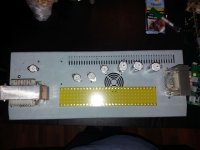
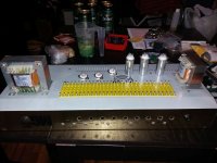
I got the parts together, now thinking about the layout.
Considering heat and weight reasons Im thinking about flipping the original box upside down, so the chassis will be sitting on the bottom of the box, tubes and others facing upwards. This way the weight will be sitting on the legs of the head, not pulling the top panel. Also the heat from the tubes can go up and out, instead of cooking everything under the chassis.
Any objections, problems that I do not see in advance?
From what info I gathered, I have came up with the component layout on the pictures. PT is on the left, behind it is the socket for the optional EZ81. Next to them are the sockets for the 2xEL84 (with option to fit 2 more if desired) and then the ECC81 of the effects loop, then the ECC83s of the preamp and the output transformer on the far right.
Could this work out properly?
As always thanks for your opinions and advices!
Attachments
As far as I got reading here and there, I reckon that 6P14P is a drop in replacement for EL84, and 6N2P can be use instead of ECC83s, if I modify the heater circuit for the correct pinout (or use a socket converter); am I right?
Yes. I had experience replacing EL84 in Peavey Classic 30 with 6P14P without modifications in the scheme. Just changed one tube to another and it worked fine.
To replace ECC083 with 6N2P, you need to change the connection scheme of pins 4, 5 and 9. Pin 9- grounding, pins 4 and 5- 6.3 volts.
Last edited:
Thanks for the answer Sonic, in the meantime I did my research about the topic and found out the same.
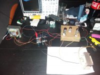
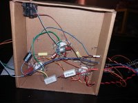
The iron has arrived and I had a little time, so whipped up a fast prototype for measuring and getting a feel for this PP thing.
Its late here as always, when I want to make noise so just did a quick test, the circuit seems to work fine with the russian tubes. But the feedback already bursted it into oscillation, so this build will be fun too.
WARNING: Extreme shock and fire hazard on the images
The iron has arrived and I had a little time, so whipped up a fast prototype for measuring and getting a feel for this PP thing.
Its late here as always, when I want to make noise
so just did a quick test, the circuit seems to work fine with the russian tubes. But the feedback already bursted it into oscillation, so this build will be fun too. WARNING: Extreme shock and fire hazard on the images
Attachments
Last edited:
- Status
- This old topic is closed. If you want to reopen this topic, contact a moderator using the "Report Post" button.
- Home
- Live Sound
- Instruments and Amps
- VOX style EL84 PP amp questions