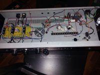
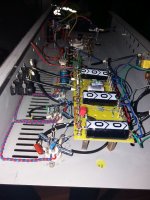
You have lots of long wires running everywhere, and no grounded metal nearby. This means lots of stray capacitance everywhere. In effect, you've added hundreds of little picofarad capacitors, randomly connecting just about every circuit node to every other circuit node....the feedback already bursted it into oscillation...
Add to that high voltage gain, and high circuit impedances, and big metal plates (electrodes) inside each tube acting as receiving antennae, and it's no wonder you have oscillation problems!
")
If your final build uses the shortest possible wire lengths, and plenty of grounded metal nearby to reduce capacitive coupling between circuit nodes, and careful layout, I think you will have much less trouble with oscillations.
These ancient "classic" circuit construction techniques - tagboards, turrent boards, tag strips - have major weaknesses. Putting rows of passive components neatly side-by-side and close together creates lots of stray capacitance. Running dozens of several-inch-long wires from tagboard to off-board components creates dozens of receiving antennae to pick up stray feedback or RF signals, encouraging oscillation.
One of my tube amps was built on a couple of rectangles of 3/8" plywood, one for the preamp, one for the power amp. I cut holes through the wood to mount chassis-mount tube sockets. Almost all passive components went flat on the underside of the board, soldered directly to the tube socket lugs, and arranged somewhat radially around each tube. Large components (transformers, big filter caps) went on top of the wood, with the tubes.
There are very few wires to be seen, as the majority of components solder directly to each other (with small brass wood-screws as tie-points). Few wires are more than half an inch long - really only the ones going to the input jack, power supply, pots, and tube heaters.
This type of construction doesn't look like anything Leonidas built, but it is inexpensive, easy, versatile (you can easily add brass screws to add more components) and much better at reducing stray capacitance than traditional tag-strip / tagboard / turret-board construction. The plywood is strong and stiff, and won't flex like thin PCB material. I think this construction method combines some of the best features of traditional tagboard builds (easy repair, easy to modify) with some of the best features of PCB construction (no long dangling wires, quicker construction).
-Gnobuddy
At least somebody has guts enough to challenge the "everything Vintage style is better" MythThese ancient "classic" circuit construction techniques - tagboards, turrent boards, tag strips - have major weaknesses. Putting rows of passive components neatly side-by-side and close together creates lots of stray capacitance. Running dozens of several-inch-long wires from tagboard to off-board components creates dozens of receiving antennae to pick up stray feedback or RF signals, encouraging oscillation.
Congratulations
Get ready for the tar and feathers crowd
On construction and stability: won´t talk about "black magic" because it does not exist, but certainly there is a degree of layout and wiring savvy which is hard to express in words, so hard to explain, which you acquire along time, with practice.
In the beginning, 100% noob mode activated, I went to extremes , including using shielded wire for filaments
, star grounding everything, making small shields with bronze paper, the works, and was PLAGUED by oscillations, hum, buzz, RF pickup, you-name-it.5 years later? Could build an amp using desk lamp quality wire, maybe slightly twisting it here and there, definitely running it flat against the chassis ... and had no trouble at all.
Hard to explain, but could look at a chassis and notice: "this is wrong, will place this wire here instead of there (maybe one inch away) and problem disappears"
The old "practice makes perfect".
FWIW Old Fender amplifiers hardly ever used shielded wiring anywhere (except to-from externally mounted Reverb tank" BUT eyeletted board included apparently "do nothing" holes.
What were they for?
They made you put (unshielded) wiring through them, in my view so said wire follows a specific path known to cause least trouble, in a consistent way, so it does NOT depend on chassis assembler´s personal skills.
My point: not only grounding per se but wiring layout makes all of the difference, must be thought and done carefully.
They made you put (unshielded) wiring through them, in my view so said wire follows a specific path known to cause least trouble, in a consistent way, so it does NOT depend on chassis assembler´s personal skills.
Never thought of it that way, now I will have to review a few layouts.
Fortunately, fear of COVID-19 is keeping the angry crowd at home, so I'm safe for now.Get ready for the tar and feathers crowd
I experienced something similar with my attempts to cook. When I first tried it, about ten years ago, everything I cooked looked and tasted rather like dog-food. You could eat it, and it wouldn't kill you, but that's the best you could say about it....there is a degree of layout and wiring savvy which is hard to express in words, so hard to explain, which you acquire along time, with practice...
I'm still far from being a real cook (I never follow a recipe), but my wife is happy to eat what I cook these days. The ingredients aren't different, and it's the same cook, so it's hard to say what changed - just experience, as you say.
-Gnobuddy
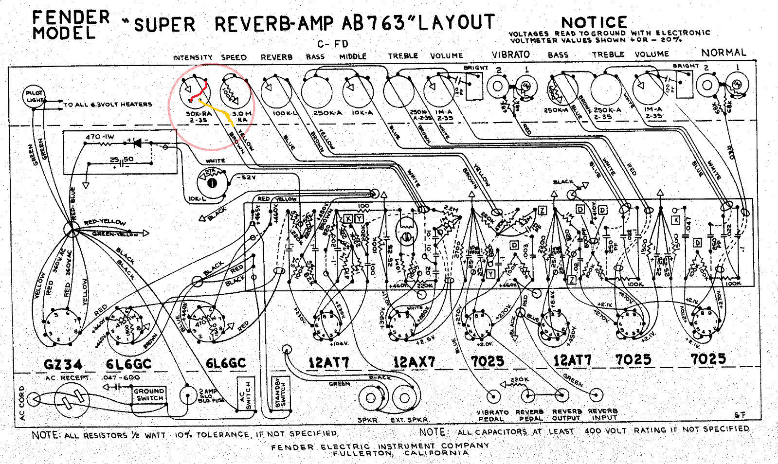
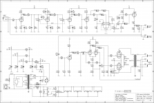
Am I right, thinking that this wire which I retraced in red, running from the effect loop send jack back to the stereo input jack; is only there to ground the output of the loop driving triode and the input of the power amplifying section, to eliminate any noises when no instrument is plugged in?
Attachments
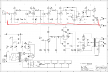
Sure looks that way to me. At any rate, I can't think of another reason for its existence.hordri said:...this wire...is only there to ground the output...
-Gnobuddy
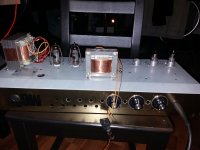
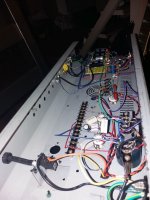
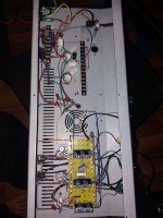
The build is slowly progressing, I have done the first tests and measurements and already have a lot of questions about biasing.
With the original shared 150 ohm resistor one of my tubes was almost instantly red plating. I have changed it to 270 ohms plus a 100 ohm rheostat and added 10 ohms into the anode circuit of both tubes for measurements. My screens were also very hot, could be seen that they are glowing red, so I swapped the screen resistors for 3300 ohms.
My idle HT is 350-355 Volts, the shared cathode resistor is 375 ohms right now.
One of my tubes idle at 14mA the other is 19mA, that gives about 5W and 7W of idle dissipation. Under fully cranked conditions this goes to 332 Volts, 26mA and 46mA, thats 9W and 16W, screen voltages are 316 and 311 Volts.
Am I correct assuming that this should be biased to stay in the maximum limits under full load?
I have used tubes which are not the best match, should I ditch the common cathode resistor and use separate ones for each tube with their own bypass caps to be able to balance the tubes better? Or play with the screen voltages to get a better match?
My OPT has UL taps, should I connect my screens to the UL taps or just leave them as on the schematic? Also max screen voltage is 300 Volts for the 6P14P, should I increase the screen resistors to drop my voltage more towards this level? (347V idle and 311-316V loaded now)
If going the UL way, should I leave the negative feedback in?
Also, the gain control pot is only effective for about 60-70% of the full turn, after that the waveform from the preamp is staying the same squared out sine, just the pulsewidth varies a little. This suggests me that I should bias V1B and V2A a bit colder, to max out a bit later. Should I play with their cathode resistors or should I try and touch the voltage dividers between the stages? (R9-R10, R13-R14)
Thanks for your help!
Attachments
> Under fully cranked conditions this goes to 332 Volts, 26mA and 46mA, thats 9W and 16W, .... Am I correct assuming that this should be biased to stay in the maximum limits under full load?
Well, yes; but are you allowing for OUTput power? Power flowing through the tubes TO the loudspeaker? In cathode-bias audio amplifiers the IDLE condition is the maximum tube dissipation.
Well, yes; but are you allowing for OUTput power? Power flowing through the tubes TO the loudspeaker? In cathode-bias audio amplifiers the IDLE condition is the maximum tube dissipation.
A cathode biased Vox is known to divert from class A when pushed. Indeed your amp is doing the same, so you have your maximum plate dissipation when amp is not pushed to its limits. If you sketch the loadline, you will see it will be over the curves at 1/3 to 2/3 of the full swing.Am I correct assuming that this should be biased to stay in the maximum limits under full load?
I'd go for separate cathode resistors, or at least part of them separated, then together.I have used tubes which are not the best match, should I ditch the common cathode resistor and use separate ones for each tube with their own bypass caps to be able to balance the tubes better? Or play with the screen voltages to get a better match?
what percentage of UL do you have? UL helps to lower your screens while playing, but for sure screen stoppers help.My OPT has UL taps, should I connect my screens to the UL taps or just leave them as on the schematic? Also max screen voltage is 300 Volts for the 6P14P, should I increase the screen resistors to drop my voltage more towards this level? (347V idle and 311-316V loaded now)
have you implemented nfb in your amp? Original design is without (it's part of its sound imo). In any case do not implement it with UL.If going the UL way, should I leave the negative feedback in?
it is quite normal for a Vox with an high output guitar. The important thing is: how does it sound?Also, the gain control pot is only effective for about 60-70% of the full turn, after that the waveform from the preamp is staying the same squared out sine, just the pulsewidth varies a little. This suggests me that I should bias V1B and V2A a bit colder, to max out a bit later. Should I play with their cathode resistors or should I try and touch the voltage dividers between the stages? (R9-R10, R13-R14)
Usually yes, but Vox are quite well known not to follow this rule, having the loadline overtaking the max dissipation plate hyperbola. Max is usually between 1/3rd and 2/3rd of the full swing.In cathode-bias audio amplifiers the IDLE condition is the maximum tube dissipation.

No, if tubes are overdriven putting out a nasty squarewave (the way Musicians use them), they are actually *dissipating* way less than at idle (if in supposed "Class A of course) .8k Raa would give maximum dissipation when the El84s are at limits of being on all the time.
Putting out maximum current? ... yes.
Dissipating maximum? ... no.
because dissipation is Current times Voltage and saturated tubes drop very low voltage across them , think 60V or so, so the product is lowish.
Your chart is fine, but shows idle voltages.
Thanks for your reply, but here we are talking about a Vox AC30, so when I say limits of class A, the sound is very far from nasty squarewaves.No, if tubes are overdriven putting out a nasty squarewave (the way Musicians use them)
At full power I agree with you, but not in this case.they are actually *dissipating* way less than at idle (if in supposed "Class A of course).
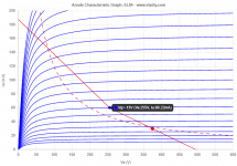
Not in this case, as maximum current is when we are in full class AB (see top left at 30V and 175ma (even if all conditions will change at that point, and most probably the g=0 curve will be way lower).Putting out maximum current? ... yes.
In this case IMO yes, please take a look at the loadline (I've already removed around 12V that are on the cathodes):Dissipating maximum? ... no.
Yes, and it's the point where 255V x 60 mA = 15,3 W versus the idle condition 375V x 30 ma = 11,25 W.because dissipation is Current times Voltage and saturated tubes drop very low voltage across them , think 60V or so, so the product is lowish.
I wasn't referring to the chart, but to the loadline. the chart was just to give reference points to plot the loadline and understand what I was saying.Your chart is fine, but shows idle voltages.
Attachments
> loadline overtaking the max dissipation plate hyperbola. Even so, max dissipation is at idle.
I think I got it. Being an hyperbola, its points go up towards left and stay almost horizontal on the right, while the loadline has a constant gradient (when in Class A) on both sides (left and right of the idle point), so the average dissipation will be in any case lower.
This is not valid if I'm in class AB and the loadline is passing over twice the max dissipation of the tube (like some Marshalls do).
Am I correct?
The title is misleading, this is now an orange dark terror copy.
I have managed to find a closer match between my tubes, also put the 100 ohm rheostat between cathodes and added 180 ohms onto the wiper. Also I have added 220u 100V bypass caps onto each cathode.
With this setup I have managed to bias the tubes at 26mA (with about 1-1,5mA drift over time, any side). This leaves me with about 9-9,5W dissipation/tube, the 70% margin is 9,8W with 6p14ps.
I have replaced the 68k on the input with 10k and 150p to ground, also moved the grid resistors on the output tubes right onto the sockets (about an inch closer), this seems to be solved my squeling, also the noise with high gain decreased.
Its coming together nicely, I have been to the guitar store and showed it to some friends too, everyone liked it much. I hope the owner will be happy too. Will get my hands on the last missing ECC81, to fire up the loop too and I will make some detailed measurements.
My newest noob question is that do I have to use separate fuses for each secondary powering my amp or can I get away with using a single fuse on the primary side? Which solution is safer regarding the trafo in the event of a real bad tube failure? (arcing, internal shorts, etc...)
I have seen examples for both, I feel I should fuse each winding separately.
I wasn't referring to the chart, but to the loadline. the chart was just to give reference points to plot the loadline and understand what I was saying.
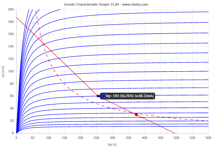
I am assuming the red dot is the idle point. And if that were the case if the amp was in Class A up to Vg = 13V, then the signal swing would cause the plate to be over dissipating from the idle point to the red dot but be under the dissipation curve when it swings from 375V to about 475V? At least that is how I understand it. And while it may be over disipating on the top half of the curve it would be cooling down on the bottom half? Or do I misunderstand things?
- Status
- This old topic is closed. If you want to reopen this topic, contact a moderator using the "Report Post" button.
- Home
- Live Sound
- Instruments and Amps
- VOX style EL84 PP amp questions