Hello,
i'm trying to understand if my moded chicken vibe works.
It's a univibe guitar pedal
here's the schematics.
What i don't understand is the intesnsity of the effect fades out as i reduce speed.
So i looked at the schematics and traced the oscillator with my scope.
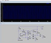
When speed is at full setting i get a nice sweep, about 4v peak to peak oscillation just before the depth pot (at C103).
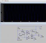
When i reduce speed, the frequency slows down so it kinda works but the amplitude of the sweep reduces too... to almost nothing at minimal speed
So here's my question, given the schematics, is it normal for amplitude to reduce with speed control ?
We're not talking about the rest of the schematics, just the oscillator part.
thanks!
i'm trying to understand if my moded chicken vibe works.
It's a univibe guitar pedal
here's the schematics.
What i don't understand is the intesnsity of the effect fades out as i reduce speed.
So i looked at the schematics and traced the oscillator with my scope.
When speed is at full setting i get a nice sweep, about 4v peak to peak oscillation just before the depth pot (at C103).
When i reduce speed, the frequency slows down so it kinda works but the amplitude of the sweep reduces too... to almost nothing at minimal speed
So here's my question, given the schematics, is it normal for amplitude to reduce with speed control ?
We're not talking about the rest of the schematics, just the oscillator part.
thanks!
Attachments
Pot section tracking.
There's just three wires to that pot? Leave the wipers alone. Swap the end wires of the two sections. Does the droop change?
Cap matching. The three 1uFd caps are assumed to be near-equal. Maybe they aren't?
And before someone complains that the oscillator has no gain: it does, but it is subtle. Which may not be helping.
When you say "grounded depth knob" was that a correction to the schematic or a modification to the circuit?
Which leads to the question: what are the transistor types?
Edit: the feedback cct is a little different to what I'm used to seeing (all the feed to the first cap). I need to dig out Horowitz and Hall again ...
Which leads to the question: what are the transistor types?
Edit: the feedback cct is a little different to what I'm used to seeing (all the feed to the first cap). I need to dig out Horowitz and Hall again ...
Last edited:
Short version: it doesn't look at all like a traditional circuit.
The traditional circuit has the emitter driving into an CRCRC circuit back to the base. Where you have a two-gang (or stereo) speed pot that creates the two 'R's, like the drawing below (but with two variable resistors,R1 and R2, not just one, )
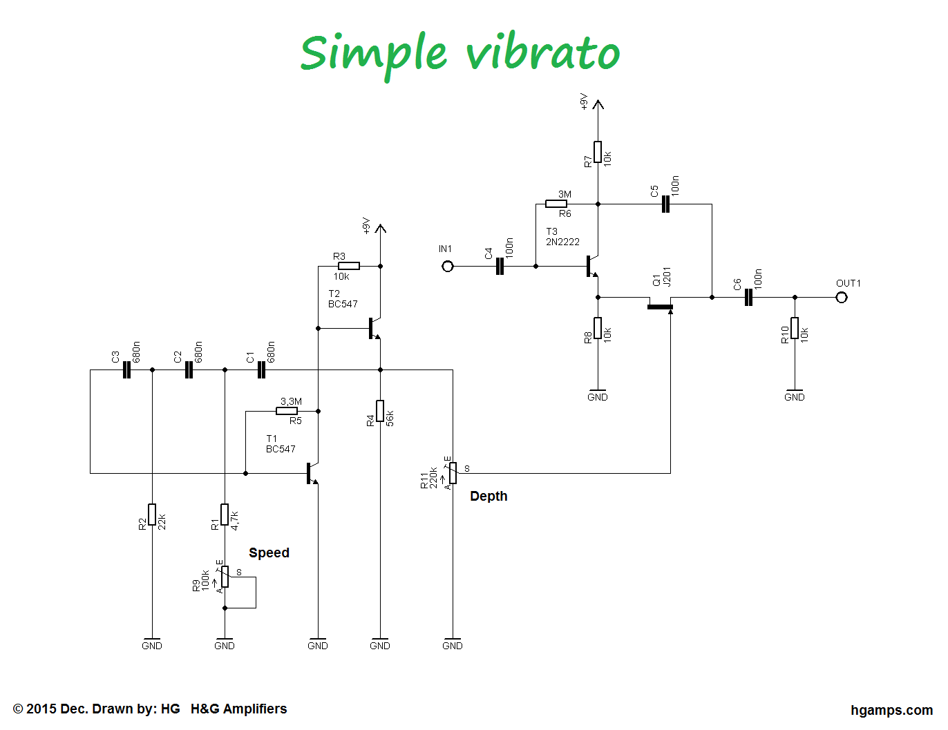
(from HG Amps
There's a pretty good description of how these work by The Valve Wizard
The traditional circuit has the emitter driving into an CRCRC circuit back to the base. Where you have a two-gang (or stereo) speed pot that creates the two 'R's, like the drawing below (but with two variable resistors,R1 and R2, not just one, )
(from HG Amps
There's a pretty good description of how these work by The Valve Wizard
Indeed! If the designer bothered to use a stereo pot for "speed", why not just use a Wien-bridge oscillator circuit? It could have been designed with about the same number of components, and wouldn't have had the weird problems of the circuit they actually implemented....Strange circuit...
-Gnobuddy
Well, they're not the only ones. I pulled a different chorus pedal out of the cupboard (OK, so I hoard guitar pedals, and it's not just a COVID-19 thing ") ) and noticed that the depth (intensity) knob alters the frequency. Not just a little bit, by nearly an order of magnitude (from below 1Hz to about 5Hz )
) and noticed that the depth (intensity) knob alters the frequency. Not just a little bit, by nearly an order of magnitude (from below 1Hz to about 5Hz )
) and noticed that the depth (intensity) knob alters the frequency. Not just a little bit, by nearly an order of magnitude (from below 1Hz to about 5Hz )You're definitely not alone in having that little problem. Pedals are to guitarists as shoes were to Imelda Marcos....I hoard guitar pedals...
Now that I play through a Boss Katana 50 most of the time, I don't use any pedals at all, so my entire small pedal stash is sitting idle in the closet.
-Gnobuddy
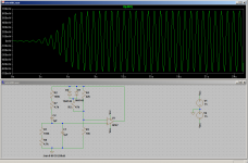
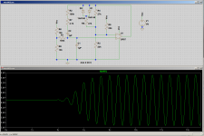
Out of curiosity, I tacked together a simple Wien Bridge circuit in LTSpice. I used the same RC values used in the Danelectro Chicken Vibe (100k stereo pot, 1uF caps, 4.7k fixed resistor), and an op-amp and bipolar supply to keep things simple for the proof of concept initial design. I also used the same crude (but effective) amplitude limiting technique, i.e. a pair of back-to-back silicon diodes in the feedback network.
LTSpice thinks it would work nicely, though I would be tempted to increase the 4.7k resistor, as the ~30Hz upper frequency limit is more than I would ever use.
Using a pair of red LEDs instead of the 1N4148s would increase amplitude to about 4Vpp. I would also make other small tweaks (mods to run off a single 9 V supply, addition of a "depth" control at the op-amp output.) With this design, there should be virtually no interaction between "speed" and "depth" controls.
This circuit is not an easy retrofit to an existing pedal, but would make sense for a clean-sheet new build. If we're going to the trouble of using a stereo frequency control pot, there is no reason to stick with the old 3R/3C phase shift oscillator. MLCC ceramic caps up to 22uF are cheap and easily available now, so there is no trouble at all getting oscillation frequencies down in the 1 Hz region with easily available pot values (100k stereo in this case.)
-Gnobuddy
Attachments
The amplifier has to be non-inverting for a Wien bridge oscillator, and it must have a voltage gain of +3 with the negative-feedback network in place....a single transistor...
With a single transistor, that means common-base is the only possible topology - common emitter won't do because it inverts the phase, common collector won't do because it has gain slightly less than 1.0.
But a CB stage has too low an input impedance to work with a Wien bridge, so it's not really workable either...
I suspect this is the reason why the 3R/3C phase shift oscillator became popular decades ago, because it would in fact work with a single triode (or transistor).
It should be possible to make a Wien bridge amp with two transistors, but I haven't managed to get it quite right yet. The challenge is getting the DC levels right. I'm probably doing something stupid, but so far, I haven't managed both single-supply operation and DC coupling throughout.
With three transistors it was easy, but IMO, at that point, it just makes more sense to use an op-amp.
-Gnobuddy
Hmm, one hell of a boot strap....maybeBut a CB stage has too low an input impedance to work with a Wien bridge, so it's not really workable either...
Spent the weekend in the garden/shed rather than on the bench so no progress from me.
As thoglette's suggestion in #8 might represent what Leo Fender once has called »Vibrato«, it ain't one. It's a tremolo that rhythmically decreases and increases the signal intensity.
The circuitry in #1 is a four stage all pass filter with it's characteristics modulated by a LDR in each stage, depending on the light from the small bulb in the oscillator. This yields a true vibrato, i.e. modulating the pitch of the musical signal.
Btw, LF consequently also was wrong in christening the Stratocaster's whammy bar »Tremolo«.
Best regards!
The circuitry in #1 is a four stage all pass filter with it's characteristics modulated by a LDR in each stage, depending on the light from the small bulb in the oscillator. This yields a true vibrato, i.e. modulating the pitch of the musical signal.
Btw, LF consequently also was wrong in christening the Stratocaster's whammy bar »Tremolo«
.Best regards!
- Status
- This old topic is closed. If you want to reopen this topic, contact a moderator using the "Report Post" button.
- Home
- Live Sound
- Instruments and Amps
- Danelectro chicken vibe - help me understand that schematic :)