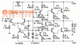
pretty generic hifi amp, not specific for guitar or bass. If you want to build something known to work, you can save three transistors and the center tap transformer and build Retro Amp 50W Single Supply - Page 22 - diyAudio which can get HD down under .1%. 50-70 v single supply.
R1 is awfully low, requires almost a power amp to drive 1.5 k. 150 k is more usual.
120 pf bc caps may limit slew rate somewhat. Needs a input cap across R1 to prevent amplification of AM sports talk radio CB band and police/fire radios. 60 pf to 120 pf. 1k resistor ahead of R1 is traditional, prevents some kind of damage.
Better check VT6 that it actually leads to output transistor idle current of 10 to 20 ma. That is the current in R13 & R14 with no input signal. May need change to R8 or R9 for each different pair of output transistors.
Lacks a inductor in series with speaker to prevent input of radio sources listed above from speaker wiring. .8 mH parallel a 10 ohm 3 W resistor is traditional.
Missing the zobel network parallel the speaker, to prevent oscillation with oddball loads. Usually 1000 ohm series .1 uf or so.
Not familiar with any of those transistors. VT4,5,6,7 better have 30 mhz Ft to reproduce top octave piano CD's accurately.
For guitar or bass pickup needs a fet stage ahead of VT1 for example TL072. Which requires additional power supply +-15 v.
Is split supply amp so any one of many possible bad solder joints would produce DC on speaker, possibly damaging it. Needs protection circuit between output & speaker, which see those threads on solid state forum. Beware many $5 ebay/amazon/ali speaker protection boards that use 2 A AC rated relays to break a DC arc of many amps. Great DC breaking relays are about $45 IMHO.
Last edited:
Yes, too low value for R1. It should equal R5 for to minimize DC offset.R1 is awfully low, requires almost a power amp to drive 1.5 k. 150 k is more usual.
The NFB loop and the CCS as they're drawn won't work. VD1, VD2 and most probably also R4 will instantly let out that magic smoke when the amp is powered, unless it works from, say, ±5 Vdc rails.
Better swap R14 to the collector of VT10 and insert a Baxandall diode/resistor combination in VT8's emitter connection.
Best regards!
Last edited:
You waited 12 years to post this?You waited four years to post that?
Fair call: it warrants some explanation. The vagueness of the original question led me to check what else Robertochanta had posted, hoping, perhaps, to findYou waited 12 years to post this?
some guidance.
But this was Robertochanta's first post, having joined four years ago.
And, as you'll know, I hold the view that "the best amplifier" is a very context sensitive question. So, to be less obtuse I'll ask again:
@Robertochanta: what do you want to use the amplifier for?
- Status
- This old topic is closed. If you want to reopen this topic, contact a moderator using the "Report Post" button.
- Home
- Live Sound
- Instruments and Amps
- Amplifier
