I suspect (but without proof at this point) that the problem is that your LM308 is unstable, and is oscillating at very high frequency (too high to hear). Fast op-amps often don't like bread-boards very much, and can be quite sensitive to layout.
Since all sorts of mysterious things keep happening with the Rat circuit, my suggestion is to start with a very basic circuit - an op-amp voltage follower - and once that's working, add on components one by one, until the whole circuit works as it should.
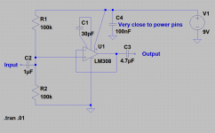
The attached screen capture shows the circuit I suggest starting with. It uses components you already have (they are all part of the Rat schematic you posted.)
If you have any pico-farad caps that are bigger than 30 pF (such as 47 pF, or 100 pF), I suggest using one of those for C1 instead of 30 pF; this will slow down the op-amp a little, and make it less likely to oscillate at radio frequencies.
Once you get it working, this circuit should behave as a clean buffer. No gain, no loss, whatever guitar signal goes in should come out virtually unchanged. And, as before, DC voltage on pins 2, 3, and 6 should all be half battery voltage, around 4.5 volts.
Get to that point first, then we can add on to it, step by step, until it becomes a Rat. Or one or both of us gives up in total frustration.")
-Gnobuddy
Since all sorts of mysterious things keep happening with the Rat circuit, my suggestion is to start with a very basic circuit - an op-amp voltage follower - and once that's working, add on components one by one, until the whole circuit works as it should.
The attached screen capture shows the circuit I suggest starting with. It uses components you already have (they are all part of the Rat schematic you posted.)
If you have any pico-farad caps that are bigger than 30 pF (such as 47 pF, or 100 pF), I suggest using one of those for C1 instead of 30 pF; this will slow down the op-amp a little, and make it less likely to oscillate at radio frequencies.
Once you get it working, this circuit should behave as a clean buffer. No gain, no loss, whatever guitar signal goes in should come out virtually unchanged. And, as before, DC voltage on pins 2, 3, and 6 should all be half battery voltage, around 4.5 volts.
Get to that point first, then we can add on to it, step by step, until it becomes a Rat. Or one or both of us gives up in total frustration.
-Gnobuddy
Attachments
I have output!!!!!
But not clear. It has a lot of noise and I can here the input in the background. One more thing that I noticed is that when I move my hand closer to the circuit without touching anything the noise increases in volume.
Voltages at pins:
2->3.7V
3->4.3V
6->3.6V
But not clear. It has a lot of noise and I can here the input in the background. One more thing that I noticed is that when I move my hand closer to the circuit without touching anything the noise increases in volume.
Voltages at pins:
2->3.7V
3->4.3V
6->3.6V
Okay, that suggests the basic circuit is correct.I have output!!!!!
The circuit may be oscillating, or just picking up electrical interference, or both. (This is why guitar FX pedals are almost always built inside metal boxes, which are grounded, to reduce noise and interference reaching the circuitboard inside.)...a lot of noise...when I move my hand closer to the circuit without touching anything the noise increases in volume.
There are a couple of things you can do that might help:
1) Is ground on the breadboard (negative end of the 9V battery) actually grounded to anything? If not, try running a wire from the breadboard ground to some grounded electrical appliance nearby, for example, the metal case of a PC.
2) Try placing the breadboard on some large grounded metal object. You can use a metal baking tray, or even a sheet of aluminium cooking foil. The baking tray or foil should be connected by a wire to the ground rail of the breadboard; a paperclip works well to make the connection if you use aluminium foil!
3) You can also invert a large metal object - a metal mixing-bowl, for example, or a large pot - over the entire breadboard, and ground it.
See if any of those things calm down your op-amp, and make most of the noise go away.
Hmm. Pin 2 & 6 should be identical (they're wired together!), and pin 3 should be within a couple of millivolts of the other two.Voltages at pins:
2->3.7V
3->4.3V
6->3.6V
I'll buy 3.6V and 3.7V - they're close enough to be identical. But pin 3 being so very different raises questions. If the op-amp is working and stable, this cannot happen; so the op-amp is either not working, or not stable...and I suspect it is the second of these. I think your LM308 is not at all happy about being on a breadboard, out in the open, without a grounded metal box around it, and is oscillating like crazy.
This is where a good oscilloscope is worth it's weight in gold (it can show you the oscillations if they're occurring), but I'm gonna guess you probably don't have one; they are expensive tools.
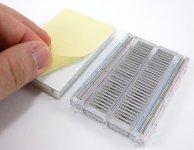
Why do fast chips have problems with solderless breadboards? If you could look inside a breadboard, you would see a collection of short metal strips, spaced about a millimetre apart, each one about 25 mm long (see attached image.) This creates lots of small stray capacitances between adjacent metal strips (which correspond to adjacent rows of holes in the board.)
The net result is as though you had wired a small capacitor (a few pF) between every two pins of the op-amp. Some op-amps will tolerate this abuse (usually slower ones, which are fully internally compensated). Other op-amps will not, and will burst into oscillation instead. I think that's what you're dealing with here.
There is a chance that putting grounded metal under and above the board, as described earlier, will calm the LM308 down. There is also a chance that moving the LM308 off the breadboard, and onto a PCB, will calm it down, because there'll be a lot less stray capacitance.
-Gnobuddy
Attachments
Indeed they do. I used aluminum foil. The signal is very low. And there are some frequencies that are about the same volume (or greater) than the input signal. There is a really high frequency noise and on really low. The output signal is lacking most of the low frequencies.See if any of those things calm down your op-amp, and make most of the noise go away.
Hmm. Pin 2 & 6 should be identical (they're wired together!), and pin 3 should be within a couple of millivolts of the other two.
I swear. I didnt change anything at all at the circuit and I dont have voltage at pin 2 and 6.
This is where a good oscilloscope is worth it's weight in gold (it can show you the oscillations if they're occurring), but I'm gonna guess you probably don't have one; they are expensive tools.
No I don't. I am willin in investing in this hobby. But I made a try a long time ago coping the Big muff pi and it tottaly failed. Now I am seeing that this project is a disaster too. I can't understand why other people copy effect pedals so easy and I am always facing problems.
Shall I solder the lm308 at a pcb and join it to the bradboard with cables?There is a chance that putting grounded metal under and above the board, as described earlier, will calm the LM308 down. There is also a chance that moving the LM308 off the breadboard, and onto a PCB, will calm it down, because there'll be a lot less stray capacitance.
When working properly, the circuit you just built has unity gain. The output should be exactly as strong as the input....signal is very low.
Frequency response should be flat, with no reduction in bass or treble.
Voltage gain is only unity (1), so there really shouldn't be lots of trouble with noise, hum, buzz, etcetera.
What are you using to provide the 9V power? Have you tried using an ordinary flat 9V battery? If all this noise you're describing comes from the power supply, using a battery instead might cure it.some frequencies...same volume (or greater) than the input signal...high frequency noise...one really low. The output signal is lacking most of the low frequencies.
One more thing: is the breadboard reasonably new, and/or have you tried building the same circuit on a different area of the same breadboard? Sometimes an old and well-used breadboard will have one or two "holes" that don't make good contact.
That must have been very frustrating....Big muff pi...totaly failed.
The Pi is a relatively complex circuit, with a lot of parts in it, and multiple gain stages. A small mistake in any one gain stage ruins the whole circuit. IMO, it really isn't suitable for a beginner to electronics.
It is possible for an adult beginner to build one, but you would have to know how to fault-find and fix your mistakes as you go.
There are almost always some mistakes when you build a circuit with that many components on a proto-board or breadboard. I'm in the middle of designing and building a project with about the same complexity as the Big Muff. Even though I have built electronics circuits as a hobby since I was 8 or 9 years old, and that was a long time ago, I still made one mistake while building my circuit, accidentally leaving out one resistor.
Of course the circuit didn't work when I tested it - but some DC voltage checks, followed by a close physical inspection, quickly revealed my mistake. I soldered in the missing resistor, and the circuit now works.
I wish I could help you more. If I lived near you, I would invite you to bring your circuit and come over, and we'd quickly get it working over a cup of coffee. But from this distance, it's hard for me to do more than guess at what the problem is. And the problems you're describing are quite bizarre ones, nothing typical that I can easily put my finger on.
No, that won't help - it's the breadboard itself that might be the problem, in combination with the old, obsolete, externally-compensated LM308 op-amp. If the op-amp is unstable and oscillating, adding longer wires will only make everything worse.Shall I solder the lm308 at a pcb and join it to the breadboard with cables?
That's why I asked earlier if you had any different op-amps to try. Chances are that a cheap and easily available op-amp like a TL072 would be more stable, and it doesn't cost much to find out (unless you have to pay lots of postage to have it shipped to you.)
Incidentally, the TL072 contains *two* op-amps on one chip, and you will only need to use one of the two for this circuit.
-Gnobuddy
This might be too late, but in case the OP is still monitoring this thread:
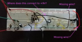
I looked at the breadboard photos from post #18 again. I can't see any connection from the op-amp to the +9V rail - is it missing? Or is it well hidden and I'm missing it?
Also, I don't see a wire connecting the two (-) rails together - is it missing? There is no internal connection inside the breadboard that does this automatically, so you have to do it with a jumper wire. Otherwise one rail will just be floating, not connected to anything at all, useless for powering anything connected to it.
And the same thing for the two (+) rails - they should be wired together. Is this wire missing? I don't see it.
If you forgot to connect pin 7 of the op-amp to the +9V rail, and/or one of the breadboards (+) rails and one of the breadboards (-) rails was not connected to anything at all, it would explain why you kept getting 0 volts on the op-amp output.
If the op-amp wasn't grounded either, and just floating, it would explain the huge amount of noise you found.
-Gnobuddy
Attachments
Still here! Never too late!This might be too late, but in case the OP is still monitoring this thread:
I looked at the breadboard photos from post #18 again. I can't see any connection from the op-amp to the +9V rail - is it missing? Or is it well hidden and I'm missing it?
It's the red jumper wire that is connected to pin 7 of the IC. The black cable that goes to the transistor is also connected to pin 7 so it has 9V.
Also, I don't see a wire connecting the two (-) rails together - is it missing?
I am connecting the two down blue rails with a black wire (under the number 30). I dont connect the upper rails to ground because I didn't use them.
If the op-amp wasn't grounded either, and just floating, it would explain the huge amount of noise you found.
Pin 4 is connected to ground through the yellow wire.
Excellent! This is such a simple circuit, and the issues you've run into are so bizarre, that I keep thinking there must be a very simple mistake somewhere. Let's keep digging, looking for it!Still here! Never too late!
Two questions:It's the red jumper wire that is connected to pin 7 of the IC.
1) Where does the other end of that red jumper wire go?
2) Where are the wires that connect the battery to the breadboard?
3) Then why is the dark green jumper connected to the top + rail at the top left corner?...upper rails...I didn't use them.
4) Also, the resistor crossing over the number 15 on the breadboard plugs into that upper + rail. Is there +9V on that rail? If so, how is power getting to that rail? I don't see the wire bringing +9V to that rail.
I did notice that.Pin 4 is connected to ground through the yellow wire.

But where is the 0.1uF ceramic filter cap that's supposed to be connected between pins 4 & 7, as close to the IC as possible? Without that cap, the IC is very likely to oscillate and misbehave.
-Gnobuddy
Two questions:
1) Where does the other end of that red jumper wire go?
2) Where are the wires that connect the battery to the breadboard?
1)The one end as aforementioned is connected to pin 7 of the IC and the other end is connected the D3, C11 positive pin C12 and R11. (in the photo is next to the on end of green jumper wire- bottom left)
2)This are the two wires at the beginning of the rails (red is +9v and black is the ground, bottom left at the photo)
3) Then why is the dark green jumper connected to the top + rail at the top left corner?
3)That's the +4.5V rail.
4) Also, the resistor crossing over the number 15 on the breadboard plugs into that upper + rail. Is there +9V on that rail? If so, how is power getting to that rail? I don't see the wire bringing +9V to that rail.
4)This resistor is R2 in the schematic.
But where is the 0.1uF ceramic filter cap that's supposed to be connected between pins 4 & 7, as close to the IC as possible? Without that cap, the IC is very likely to oscillate and misbehave.
Thats the cap 1k63 (its upside down) at the bottom right of the IC. I used a film capacitor. Is there a problem with that?
One pin is connected to the pin 4 of the IC and the other end is connected to the pin 7 through a black jumper wire.
The picture is misleading! They were connected to the same raw.
Thank you very much for your time. I am postponing this project. I created my first pedal as I said and it was big muff pie clone. I dont really like it as a pedal but I had the components. I will try the alcapulco gold next. I have some lm386 so why not?
Thank you very much for your time. I am postponing this project. I created my first pedal as I said and it was big muff pie clone. I dont really like it as a pedal but I had the components. I will try the alcapulco gold next. I have some lm386 so why not?
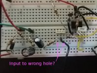
The picture is blurry and out of focus, and some of the colours are hard to see, so it's hard to tell resistor values. But are you 100% sure the input signal is actually getting to pin 3? Can you double-check if the wire really is in the correct hole? It sure doesn't look that way in the photo.The picture is misleading!
In an earlier post you wrote "The signal is very low...output signal is lacking most of the low frequencies." Both these symptoms could occur if your input wire is plugged into the wrong row, and only a tiny amount of stray capacitance in the breadboard is actually connecting the signal to the op-amp.
Even if you've abandoned this project and move on, there is value in finding out what mistake you're making in the Rat prototype. That way, you can avoid making the same mistake in future projects. Mistakes are fantastic learning opportunities!
I bought a Mooer Triangle Buff (yet another Big Muff clone) some years ago, while searching for David Gilmour sounds. Like you, I didn't really warm up to the sound of that pedal. But Gilmour got some amazingly beautiful sounds out of it, so the problem is clearly me, and not the pedal!
-Gnobuddy
The picture is blurry and out of focus, and some of the colours are hard to see, so it's hard to tell resistor values. But are you 100% sure the input signal is actually getting to pin 3? Can you double-check if the wire really is in the correct hole? It sure doesn't look that way in the photo.
In an earlier post you wrote "The signal is very low...output signal is lacking most of the low frequencies." Both these symptoms could occur if your input wire is plugged into the wrong row, and only a tiny amount of stray capacitance in the breadboard is actually connecting the signal to the op-amp.
Even if you've abandoned this project and move on, there is value in finding out what mistake you're making in the Rat prototype. That way, you can avoid making the same mistake in future projects. Mistakes are fantastic learning opportunities!
Oh! I think I wasn't clear. I am still curious of what had gone wrong but unfortunately I have not that circuit at my breadboard :/. But I will surely remake it. I bought 3 lm308 so It is not easy to fully abandon.
I have more spare time nowadays with the covid-19 so I will surely come back! Thank you vary much once more for your time!
So im back again. After succesfull pedal builds (big muff and TS9) I am buildin RAT again.
The problem is I have no output. If I connect the input to pin 6 of the IC there is a cleanish guitar sound. If I connect the input correctly it doesnt seem to work.
Refering to this schematic:
https://www.electrosmash.com/images/tech/pro-co-rat/pro-co-rat-schematic-parts.jpg
Volts at the IC pins are
1: 5.17V
2: 2.97v
3: 3.32v
4: 0.032v (I suppose its zero but its the mutlimeters error)
5: 2.94v
6: 3.04v
7: 7.18v
8: 6.33v
PS1. I bought a new multimeter which has 10ΜΩ input impedance.
PS2. I had a bunch of potentiometers (100k) and when i measure the ohm resistance between lag 1 and 3 and my polymeter shows higher resistance (like 500-600k) is there an explanation for these or have alll the pots been destroyed?
According to the voltages you reported, pins 2,3, & 6 are now all at (approximately) the same voltage. It looks as though your op-amp is working.Is there a way to check if LM308 is working?
I would like to help, but I have no explanation to offer for the symptoms you report.
You should get virtually no signal when you connect your guitar direct to the op-amp output; it should have almost the same effect as grounding your guitar signal.
Same thing with the pot measurements. It wouldn't be terribly unusual for a 100k pot to measure 20% high or low (80k - 120k). But 500k for a nominally 100k pot is ridiculous. No reputable vendor would sell you pots like that. There is no reasonable way in which you could have damaged all those pots to produce your observed results, either.
I have no LM308s, as they are old, slow, and troublesome op-amps. If I did, I would breadboard your circuit, get it working, and send you photographs to follow.
-Gnobuddy
Excellent news! Congratulations!I used a dual op amp (specifically the TL072) and used only the one channel and it works!
If you go back and re-read my post #25, I suggested trying exactly this (using one half of a TL072).
Unfortunately, there are lots of fake electronics parts available now. To avoid them, I only buy current-production parts from reputable vendors (in North America, that means Digikey, Mouser, et cetera.)...3 LM308N from banzai that dont work...
Where did the defective potentiometers (the 100k ones that measure 500k) come from? Also Banzai Music?
A friend of mine bought a box of pencils from a dollar-store here. He got home and found no lead (graphite) in the pencils at all - they were just solid wood! Fake pencils!
I can't even imagine what kind of person would go to the trouble of manufacturing fake pencils.
-Gnobuddy
- Status
- This old topic is closed. If you want to reopen this topic, contact a moderator using the "Report Post" button.
- Home
- Live Sound
- Instruments and Amps
- Proco RAT Clone doesn't work