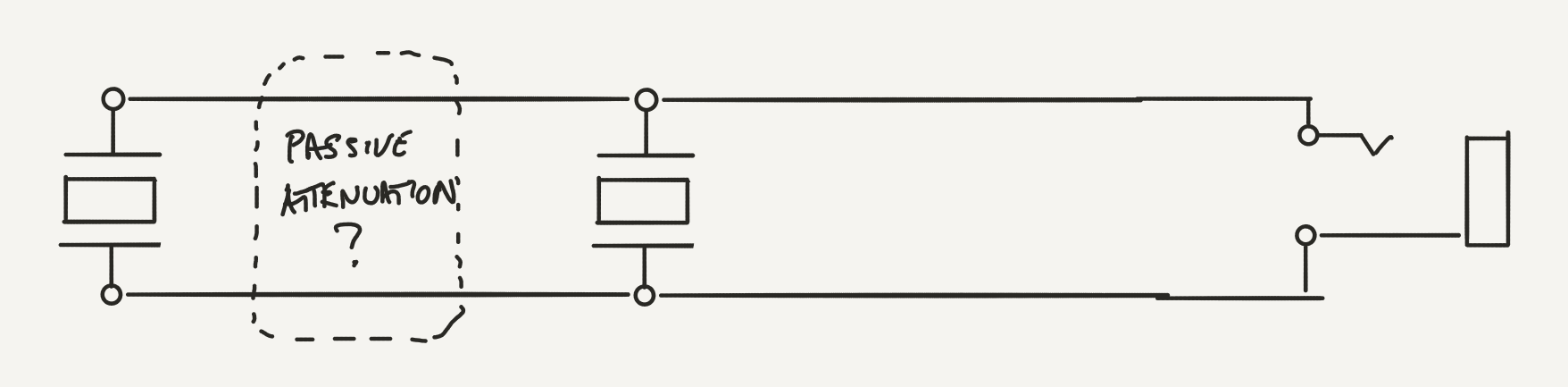
Hi, for background, I play upright bass and am using a yamahiko dual sensor pickups. these replace the adjuster wheels of the bridge.
The stock configuration is that with a bridge cable, they are connected in parallel. and the signal then goes to a preamp with 10+ Meg Ohm input impedance.
By using two separate cables into a two channel preamp, I find I prefer the balance favoring one side or the other but this comes at the cost of complexity of outboard gear.
Is it possible to connect the two piezo sensors together with a passive attenuator between them such that I get a similar result to using the two separate channels with unequal blending? I suspect that any un buffered attenuator between them will attenuate both sensors.
Attachments

Someone may have a much better idea, but here is what comes to my mind. And I must report I have not had my lunch yet.
First experiment. They are now in parallel. If we were to place a resistor in series at the output, it will form a voltage divider with the amp 10M. So we need to know how much we can use, because that would lose some signal level. Lets say with no resistance that is 100% signal. Wire up a 1M pot as a variable resistor, and insert it in the signal line serially. DO this outside the instrument. Now dial it down until you get the overall level to the lower limit of what you might think useful for balance. Just for argument, let's say that is 100k.
Now what I would propose would be to break the wire between the two pickups on their hot side - just above the word "passive". And insert there a 100k pot, one end to each piezo. Now wire the pot wiper to the output jack. Now the pot is a balance control.
There may be issues I have not considered.
Alternate plan. leave one pickup wired direct to jack, and the one you want to dial down, add that 100k pot in series with it and the output. Basically put my 100k pot in the same place as above, but wired as a variable resistor. Leave the jack wire as it is now.
My value was chosen at random, you need to determine what works.
ah - right. I was thinking of traditional attenuators that have a resistor to ground (either "T" or "H" design).
but you suggest just putting a resistor inline on the hot side will reduce how much the first piezo contributes to the overall signal without degrading the second piezo signal.
Cheers
but you suggest just putting a resistor inline on the hot side will reduce how much the first piezo contributes to the overall signal without degrading the second piezo signal.
Cheers
Essentially, yes. A little experimentation to determine what range of resistance works best. You can make it a pot for adjustable, or a simple resistor for a permanent balance. My choice would be temporary pot to dial in the desired amount, then measure the pot to select a resistor.
Your L-pads, and H or T circuits work with lower impedance things, but piezos are pretty much a cap electrically.
Your L-pads, and H or T circuits work with lower impedance things, but piezos are pretty much a cap electrically.
I have a different hunch!
Piezos are electrically close to being like capacitors, so caps may be a better component type for balancing without throwing off tone. A cap in series with the piezo that you want to attenuate would do it. What value? not sure but, the capacitance of a biggish piezo disc is about 20nF. Need to try a range, maybe that as a max and then trying smaller.
Piezos are electrically close to being like capacitors, so caps may be a better component type for balancing without throwing off tone. A cap in series with the piezo that you want to attenuate would do it. What value? not sure but, the capacitance of a biggish piezo disc is about 20nF. Need to try a range, maybe that as a max and then trying smaller.
That is what I would suggest as well.I have a different hunch!
Piezos are electrically close to being like capacitors, so caps may be a better component type for balancing without throwing off tone. A cap in series with the piezo that you want to attenuate would do it. What value? not sure but, the capacitance of a biggish piezo disc is about 20nF. Need to try a range, maybe that as a max and then trying smaller.
You could also wire both PU in series and connect parallel caps to the one you want to attenuate.
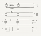
Before you go series, try wiring them in series first as an experiment. Just as a guitar often has a switch to put pickups in series for the changes in tone, I would expect phase cancellations and other artifacts from a series circuit
Piezos ACT like caps a lot, but they are not caps. All these ideas are worth trying. Once you can access the wiring, then it is simple enough to try them, but be aware of the other factors.
Piezos ACT like caps a lot, but they are not caps. All these ideas are worth trying. Once you can access the wiring, then it is simple enough to try them, but be aware of the other factors.
The biggest issue I see is that the ground end of the crystals are mated with the case (shield)
I can do #1,2 easily enough but I can’t do #3 and maintain a properly shielded circuit.
Once I have all the parts, I can try the third one but it won’t fly for gigs because of the noise
I can do #1,2 easily enough but I can’t do #3 and maintain a properly shielded circuit.
Once I have all the parts, I can try the third one but it won’t fly for gigs because of the noise
I used to design piezo input MI amplifiers, you can place a capacitor in parallel and this will attenuate the signal, but also has the potential disadvantage of extending the LF response - if this is problematic, reduce the input impedance by approximately the ratio of the piezo and parallel capacitances. (so if adding a parallel cap doubles the overall capacitance halve the input impedance)
I like Enzo's suggestion, post #2. In fact, when I read your post #1, I had exactly the same idea; then I saw that Enzo had already suggested it in post #2. Not the first time Enzo's been far quicker off the line than I have.Is it possible to connect the two piezo sensors together with a passive attenuator between them such that I get a similar result to using the two separate channels with unequal blending?
")
But I realized I didn't know exactly how this idea would behave with piezo sensors (with their capacitive output impedance.) Would the mix pot now cause changes in the frequency response of the sensors?
To answer that question, we need to figure out how a piezo sensor behaves, and then see if we can simulate its behaviour in this circuit.
Well, a piezo sensor physically *is* a small capacitor - a thin insulating material with metallisation on both surfaces, i.e., a thin dielectric with metal plates on both sides of it: the very definition of a parallel-plate capacitor.
When the piezo is deformed, an electric charge is induced on the capacitor. The usual capacitor charge equation Q=CV applies; the voltage across the capacitor V is therefore Q/C, and is proportional to the amount of stress (bending, roughly speaking) applied to the piezo.
If we connect no load (or a very light load, i.e. very high impedance) to the piezo, this equation for V will hold all the way down to bass frequencies. However, if the resistor is too small, it will drain away the charge Q quickly, before bass cycles have time to complete, and the bass response will suffer.
We can model this electrically by representing the piezo as an audio frequency AC voltage source in series with a capacitor. As mentioned previously, the capacitance depends on the size of the piezo. The 20mm discs I have are specified at 13 nF (0.013 uF) each. Bigger piezo discs are often 20 pF. Those narrow undersaddle piezo strips used in guitars have much smaller capacitance.
I found some information on your Yamahiko pickups online, and it looks like a pair of piezo discs; neither the diameter nor the capacitance is specified, but the discs aren't tiny, so it's a safe guess that you have more than 10 nF capacitance per sensor (and maybe twice that.)
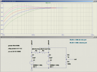
Now we have enough information to model Enzo's idea in LTSpice. I used 13 nF per sensor for the simulation. A 500k linear mix pot is wired between the two piezos, and the wiper of the mix pot feeds a 500k log volume pot.
LTSpice lacks a built-in potentiometer symbol, so I model them using a pair of resistors and some simple algebra. R3,R4 is the mix pot, with their junction being the pot wiper. The two equations "turn" the potentiometer in steps, so that we can see how pot rotation affects (a) the signal coming out of each piezo, and (b) the signal coming out of the volume pot (R1,R2).
The attached screen capture shows what happens to the output of the first piezo sensor (V1, C1) as the "mix" pot is turned. Surprise - there is actually a bass boost at some settings, though a fairly small one, just over half a decibel. By pure coincidence, the peak of the bass boost falls smack bang on the tuning frequency of the low "E" string of a bass, at 40 Hz.
Turning the mix pot to the other extreme causes a bass droop of almost 2 dB at 40 Hz. A bit more concerning than the half-dB bass boost.
Of course exactly the same thing happens at the output of the second piezo sensor (V2, C2).
In my next post I'll show what happens at the output of the volume control. There is another surprise there.
-Gnobuddy
Attachments
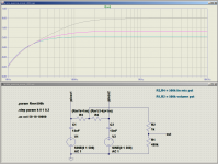
This time I plotted the frequency response at the wiper of the volume pot, i.e. the signal that comes out of your pickup and which gets fed to your preamp.
As expected, there is some slight bass loss due to the piezo capacitance. When the "mix" pot is centered, there is about a 2 dB signal loss - not very much. Dialing the pot either way from centre raises the output level slightly, while, of course, altering the balance of one pickup with respect to the other.
There are only 3 curves on the graph instead of 5 because of this symmetry - while the simulation steps the pot through 5 equally spaced positions, the two upper curves overlay perfectly in the mix-left and mix-right positions, so you only see separate curves for the centre position, and the two positions left of centre. (Curves for right of centre exactly overlay the curves for left of centre.)
There's about 2 dB bass cut at 40 Hz. I have no experience with double-basses, but on my bass guitars, this would not concern me at all - in fact I frequently high-pass the bass guitar at 60 Hz or higher, which makes it sound less muddy. Of course you may have a different opinion.
-Gnobuddy
Attachments
Well, your theory is stronger than mine. But wouldn't your 500k volume pot disrupt the 10M input impedance of the amp? leaving the balance pot, but eliminating the volume control - and saving the 10M input, what does that do to the simulation? I mean if it works fine with the 500k, fine, but for academics wouldn't it be even more transparent without?
I used to design piezo input MI amplifiers, you can place a capacitor in parallel and this will attenuate the signal, but also has the potential disadvantage of extending the LF response - if this is problematic, reduce the input impedance by approximately the ratio of the piezo and parallel capacitances. (so if adding a parallel cap doubles the overall capacitance halve the input impedance)
As a side note - Upright bassists commonly use a high pass filter to roll off the low frequencies. the low frequencies tend to be overly expressed when amplified.
Some bassists discovered that a variable impedance preamp could act in some ways like a high pass filter.
they're plugging the yamahiko into a Sarno Black Box with variable input impedance from 1M to 20M and using the impedance as a high pass filter.
Thanks for your write up Gnobuddy! I'm going to have to re read it several times before I feel like I understand.
You might be right.. These pickups are a little mysterious. but I was led to believe it uses a thick crystal in the shaft instead of a flat disk piezo.
With the thick piezos (2-3mm), I would think capacitance may not have as significant an effect.
I found some information on your Yamahiko pickups online, and it looks like a pair of piezo discs; neither the diameter nor the capacitance is specified, but the discs aren't tiny, so it's a safe guess that you have more than 10 nF capacitance per sensor (and maybe twice that.)
-Gnobuddy
You might be right.. These pickups are a little mysterious. but I was led to believe it uses a thick crystal in the shaft instead of a flat disk piezo.
With the thick piezos (2-3mm), I would think capacitance may not have as significant an effect.
- Home
- Live Sound
- Instruments and Amps
- inline attenuator of dual piezo pickups