This is a bus ground, and I agree with cobretti that it can work just fine, particularly in a preamp, where all currents are small (just a few milliamperes.)...if all components are laid out and wired in straight line as seen on the picture I highlighted red, there shouldn't be a conflict with current flow.
Sometimes a few slight modifications to a bus ground - converting it more into a "star of stars" system - can help to lower hum, when higher current stages are included in the picture. (Bigger currents cause more noise voltage when flowing through ground wires.)
IMO, when it comes to grounding problems, the single worst offender in a valve guitar amp is the main power supply filter cap ground, and that one isn't shown in these partial schematics in this thread. (But Merlin Blencowe address it in his write-up that I linked earlier.)
There are relatively big current spikes - up to hundreds of milliamps - flowing through that filter cap, and if it's grounded to the wrong point, that can inject considerable hum and buzz into the amplifier. (The situation is worse with solid-state amps, where filter cap ripple currents might be amperes rather than tenths of an ampere.)
That filter cap should ground directly to the main star point, and the preamp should arrive at that same star point separately, by its own wire. Never share a length of ground wire between the preamp, and the main power supply filter cap.
-Gnobuddy
Gnobuddy the hum stops when I unplug mains power so it is 1,3,4,5 or 6. Out of these my focus is now on 1 and 3. Are higher gain amplifiers more sensitive to ripple than lower gain ones? The amp does not ghost.
Power transformer too close to input valve .. hmm does it matter if the primary of the secondary is facing the preamp tube? I have the pt on the complete opposite end of the chassis related to the preamp tube.
Dreamth the center tap of the heaters is elevated.
Cobretti I tried bus grounding it in the past the wat you have it drawn. The results were about equal to star grounding.
Turk182 what do you mean exactly by test conditions?
It wouldn't hurt probably to dismount the transformer and place it away from the enclosure to see what happens with the hum noise. You would have to (most likely) carefully and "safely" extend transformer taps for this test. I also sometimes try to hold and move around on top of the chassis a thick metal plate or even thick aluminum or copper sheet plate between transformer - caps and tubes mounted on the chassis, and kind of try to position it in different angle and distance from the transformer to attenuate the magnetic field, hum. This works like a shield and might help you to locate the leaky magnetic field and give you direction where the magnetic field is most problematic, strongest. Another problem with commercially available transformers is that they have high magnetic saturation. I built SS stereo amp a few months back with Triad 100VA 2x24V toroid transformer and couln't make it work hum free feeding both channels. I had to order custom made transformer from Canada from SumR. It usually requires less core saturation, like 1.2-1.4T.
Yes, because some of the ripple on the B+ to the input valve will appear at the anode of that valve, and then be amplified by all the subsequent gain stages.Are higher gain amplifiers more sensitive to ripple than lower gain ones?
The same thing happens if there are problems with the grounding scheme; if any ripple voltage is generated in the ground wire (due to ripple current flowing), that too will be "injected" into the input stage, and then amplified by all the subsequent gain stages.
Probably not, though there is sometimes one position where the hum is lower. You can't always predict what position that will be, sometimes it's at some weird angle. I have an old Bogen P.A. with a transformer mounted rotated 45 degrees with respect to the other.Power transformer too close to input valve .. hmm does it matter if the primary of (or?) the secondary is facing the preamp tube?
That's usually a good place for it, as far as possible from the sensitive input circuitry.I have the pt on the complete opposite end of the chassis related to the preamp tube.
Is the hum due to ripple voltage or grounding flaws? If your rectifiers (you didn't mention if solid-state or valve) will tolerate a bigger main filter cap, try paralleling another big electrolytic cap with the main filter cap. That will reduce ripple voltage (but also worsen ripple current spikes!), and depending on how your amplifiers hum problem responds, that might tell you if the problem is too much ripple voltage, or too much ripple current in the wrong place.
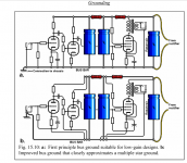
I'm attaching three snippets from Merlin Blencowe's chapter on grounding, in case they might help. The second idea - adding an additional resistor in the *ground* line between the main filter cap and the secondary filter cap - helped in one of my builds.
The third idea shows how the simple bus ground can be improved to the "star of stars", and also note where the one-and-only connection from amplifier circuitry to chassis ground is made: not at the power supply filter cap, but at the input jack! (This is in addition to the safety ground, which is made from the ground lug of the AC inlet socket directly to chassis metal nearby.)
If you try moving any sort of grounded metal plate around near chassis components, as Cobretti suggested, PLEASE take great care not to electrocute yourself in the process! Wear thick insulating gloves, hold the metal with a pair of electricians pliers, wear safety goggles in case of a shower of sparks, maybe stick the metal inside a heavy-duty Ziplock bag with only the ground wire emerging. You do NOT want to take the chance of the metal coming into contact with any dangerously high voltages.
I'm not sure I would go the route of extending wires and moving the power transformer, either. I think the new longer wires might create more problems, and may not reveal anything helpful. The power transformer, rectifier(s), and main filter cap should all be close to each other, as this is the area where the largest and nastiest currents flow.
-Gnobuddy
Attachments
what are you driving the input with to perform this test?Turk182 what do you mean exactly by test conditions?
ok thanks for confirming that!
would or does placing a metallic cover over the open side of the chassis reduce noise at all?
i've got a fluorescent magnifying lamp on my bench that's a broadband noise emitter that induces noise like heck (sort of useful when i want to check shielding)
sorry if i seem pedantic but when tracing circuit noises overlooking things like whether or not the input is grounded can lead anyone astray, i spent time looking elsewhere for a noise source after confirming to myself the the tip point of a jack was seeing ground (measured across the jack) it wasn't till i removed the pc board to find a cracked solder joint to jack "ground" and indeed the input was floating!
If you try moving any sort of grounded metal plate around near chassis components, as Cobretti suggested, PLEASE take great care not to electrocute yourself in the process! Wear thick insulating gloves, hold the metal with a pair of electricians pliers, wear safety goggles in case of a shower of sparks, maybe stick the metal inside a heavy-duty Ziplock bag with only the ground wire emerging. You do NOT want to take the chance of the metal coming into contact with any dangerously high voltages.
-Gnobuddy
In no way I suggested to stick the metal plate inside the chassis full of live components!
I think and hope people have some degree of sanity to know that this would be dangerous act and wouldn't do that. Rather above the chassis where tubes are sticking out.
But what I was suggesting with placing the PT away with extended wires just to see if the magnetic field of the transformer is the culprit.
Last edited:
Thanks for clarifying that!...above the chassis where tubes are sticking out.
-Gnobuddy
JimvdB, have you any equipment to measure the hum level, and have you grounded each stages grid input, as a first-in way of identifying if the hum is related to specific stages, as per post #26 suggestion?
Having a measurement tool and making benchmark tests on hum levels as you change things is a good way to progress. Making some simple diagnostic measurements, such as isolating stages, may quickly identify a fault or a stage to focus attention on.
Having a measurement tool and making benchmark tests on hum levels as you change things is a good way to progress. Making some simple diagnostic measurements, such as isolating stages, may quickly identify a fault or a stage to focus attention on.
Hi
The DCed heater approach used in mesa and other amps is pretty brutal to the heater winding of the power transformer. It sounds like in your case the reference for the heaters has been lost.
I've seen other amps where the preamp heaters are DCed as you describe, but additional high-value eletros are placed from each side the "6Vdc" to ground, with polrities carefully oriented since that looks like +/-3V.
It is a lot simpler t use the DC-stand-off K O'Connor shows in The Ultimate Tone volume 3 book. I did this in my Marshall and heater noise vanished. All the heaters run on AC like stock, but are referenced to about 60Vdc instead of ground. before this, i rewired the amp according to kevin's ground method and was left just with the heater noise, which the stand-off cured. he says the standoff provides the same amount of hum reduction as brute force DCing but it's way cheaper. It definitely works !!
I upped the mains filter cap to 100uF coming from 50uF. No change in hum. The amp does feel tighter which is kinda cool.
Trobbins I don't have a scope nor a spectrum analyser unfortunately.
Turk182 I wish it was a fluorescent lamp.
Gnobuddy the resistor in the ground line sounds cool but I have a choke there.
Nauta the heaters are already elevated.
Cobretti I will try to find a metal plate.
What I did notice today is that the hum gets less with the master at full. Is this a clue?
JimvdB, do you have a meter that can measure AC volts, and hopefully AC millivolts?
If so then along with your ears you have a simple measurement capability. I'd recommend post #27 process of shorting the signal input to each stage in sequence and recording the ACV on the output (with resistive load). You can use volume/gain pots in between stages to quickly check levels, but that leaves some doubt about wiring to pots etc, so best to solder in a short link from grid to the cathode 0V node for that stage.
Can you record a signal somehow - such as via microphone, or DI, to a computer and save as a digital file. You can then use free audio software to look at the recorded waveform, and software spectrum analyser to see the signal frequencies. I've even done that using an Android phone with free spectrum analyser software to see what the microphone is receiving.
Yes...it suggests the hum voltage is at the ground end of the master volume pot, rather than at the "hot" end. In other words, it suggests problems with grounding, rather than problems with B+ ripple....the hum gets less with the master at full. Is this a clue?
IMO Trobbins has made the best fault-finding suggestion - do consider following his advice!
-Gnobuddy
Trobbins do I understand it correct that grounding a grid grounds out any signal that comes before that point?
What would I look for on the recorded waveform?
Gnobuddy I thought grounding problemen were excluded by you as a possible cause in post 38. The amplifiers doesn't hum just after I pull the mains plug.
What would I look for on the recorded waveform?
Gnobuddy I thought grounding problemen were excluded by you as a possible cause in post 38. The amplifiers doesn't hum just after I pull the mains plug.
Yes the reason to temporarily solder in a link between input grid and that stage's 0V node (where the cathode resistor and local B+ bypass cap connect at one point), is to hopefully suppress any noise/hum coming from circuitry or wiring loops before that point. Care is needed to recognise that some stages may not be typical cathode bias triode stages, and so 'signal shorting' their input may require extra thought.
The output signal from the amp in to a resistor load should only have noise and some hum frequencies on it.
A scope is one measurement means, but that has to be done properly to avoid 'seeing' hum that isn't from your amp but rather from your scope probe connection or earth loop to your scope. If the hum frequencies are significant then you may see some signal other than a 'straight line' of noise. You likely have to use the highest vertical gain setting on the scope, or a lower attenuation probe.
I strongly suggest also doing an AC voltage measurement, and identifying the meter you are using. Measured levels may well be 0mV, or whatever the meter can resolve, but should increase (perhaps in to the volts region) as more stages are included, and any gain/vol pots are maxed. If there is an unwanted coupling within the amp, then the amp output could rise significantly and cause the amp to max over-drive, so some care is needed (and hence the need for a resistor load that is rated for the amps output power).
It is likely that the hum/noise level would increase as you include more amp stages in the setup. Each stage has an AC signal gain, so any identifiable hum signal would typically increase by the gain of each extra stage you include, if for example all the hum originated at the first input stage.
Last edited:
Well, let's think this through. At first I thought no hum when the plug was pulled pointed to power supply ripple being the issue - but two new bits of data have surfaced since then: one, the bigger filter cap didn't help. Two, you said the amp hummed more with the master volume at zero.Gnobuddy I thought grounding problemen were excluded by you as a possible cause in post 38. The amplifiers doesn't hum just after I pull the mains plug.
So: there's no hum when the mains plug is pulled, i.e. when the amp is powered by clean DC, and there is no AC from the transformer.
And when the amp is plugged in, hum is worst with the master volume at zero, which tells us that the hum voltage is in the ground wire (because that's where the pot wiper goes when the volume is turned down.)
I think this means that when the transformer is powered on, it's somehow injecting noise into the ground path for the master volume.
There's more than one way this could happen. A common cause is the spiky ripple current from the filter capacitor accidentally sharing a ground wire with the master volume. A less common one is AC current induced in the ground wire caused by the transformer magnetic field. It could even be a ground loop inside the amp that's picking up the magnetic field from your power transformer. But I think it is a ground layout or wiring problem.
-Gnobuddy
It could even be a ground loop inside the amp that's picking up the magnetic field from your power transformer.
-Gnobuddy
Not 100% sure, but that's what I think it is. Magnetic field being picked up.
- Status
- This old topic is closed. If you want to reopen this topic, contact a moderator using the "Report Post" button.
- Home
- Live Sound
- Instruments and Amps
- DC heater noise