Sanity check. So the output impedance of an EL84 is 4k ohms. For a push-pull which has two tubes, this gives me 8k ohms. So for an output transformer, am I correct in assuming I want the transformer to have an input impedance of at least 8k ohms?
Also is there a recommended resource for building the power output stage? Meaning from the input of a LTP to the speaker? I sort of have a rudimentary understanding of the pre-amp, the rest is really shaky.
Also is there a recommended resource for building the power output stage? Meaning from the input of a LTP to the speaker? I sort of have a rudimentary understanding of the pre-amp, the rest is really shaky.
Right, here's an example of an amp like you are talking about.
http://www.ampwares.com/schematics/marshall/marshall_18watt_schem.pdf
http://www.ampwares.com/schematics/marshall/marshall_18watt_schem.pdf
Last edited:
Thanks! It is a good schematic, I think my trouble is I just I don't know what T2 is. For example which would I pick out of Edcor's lineup (my guess is CXPP21-8.6K):
CXPP30-10K
CXPP21-8.6K
CXPP25-3.4K
CXPP25-2.5K
CXPP25-1.6K
I'm probably being stupid, but similarly I don't know why C16 is 0.01uF and R15 is 470K. I get the cap is removing the DC, but after playing around with Baxandall tone-stacks, I know it is more than just simple filtering and biasing. I've got a big hole in my grasp of the theory. :/
No.Sanity check. So the output impedance of an EL84 is 4k ohms.
That is a blanket statement which means nothing by itself.
In fact, being a pentode, EL84 "output impedance" is way way higher than that ... but that´s not the point.
If you are talking a power amplifier, tubes will "see" a certain load impedance.
Whose value is neither "fixed" nor random, but calculated for optimum performance, depending on many factors.
NO. It does not work that way.For a push-pull which has two tubes, this gives me 8k ohms.
There is one EL84 push pull circuit which uses/specifies 8k plate to plate impedance; that is not a random number but a calculated one nor it ios a "one size fits all" magic number.
And one of those EL84 does not "see" 4k but 2k load, go figure.
It depends on the project you will build.So for an output transformer, am I correct in assuming I want the transformer to have an input impedance of at least 8k ohms?
In principle, build a tried and true circuit, there are a few around.Also is there a recommended resource for building the power output stage? Meaning from the input of a LTP to the speaker? I sort of have a rudimentary understanding of the pre-amp, the rest is really shaky.
On a parallel path, read a book or two about Tube power amp design.
And, good luck with your project.
")
Last edited:
There is one EL84 push pull circuit which uses/specifies 8k plate to plate impedance; that is not a random number but a calculated one
Ah, ok. I get it. I'm going about this wrong

The transformer is the load the PP stage sees. I have the EL84 anode graph, and for a given transformer, I can see how I'd draw out the load lines for it. For the design I have, if I read this right, it looks like 8k does work - if I had used a 4k OPT, the current draw would be too high, I'd have melted the tubes.
Thx!
For a push-pull circuit the output device sees half the impedance of the load since the mid-point of the load is at AC ground.
So a CT primary that looks like 8k (across the whole winding) the output devices each see 4k.
The ac impedance seen between the certre tap and one side is 2k but that's irrelevant as no AC current flows from the centre terminal - that is only relevant if using just one side of the winding.
So a CT primary that looks like 8k (across the whole winding) the output devices each see 4k.
The ac impedance seen between the certre tap and one side is 2k but that's irrelevant as no AC current flows from the centre terminal - that is only relevant if using just one side of the winding.
Last edited:
Sorry but NO.For a push-pull circuit the output device sees half the impedance of the load since the mid-point of the load is at AC ground.
So a CT primary that looks like 8k (across the whole winding) the output devices each see 4k.
Each output device sees half the *turns* or half the *voltage* and a quarter of the *impedance*
The ac impedance seen between the certre tap and one side is 2k but that's irrelevant
on the contrary, it´s VERY relevant.
So much so, that it´s precisely the load value found when drawing the tube load curve, go figure.
Nothing is morte relevant than that.
The primary parameter found is the tube load , going from maximum voltage-minimum (idle) current, to minimum (saturation) voltage- maximum current; the secondary parameter (as in developed from the primary one) is plate to plate impedance, is 4 times as much (2X turns=4X impedance) and is popular because it´s a simpler way to name push pull OTs.
Who says it doesn´t?as no AC current flows from the centre terminal - that is only relevant if using just one side of the winding.
AC current is pulled from the power supply and fed to the speaker, through the OT of course.
Just a particular case happens in perfectly balanced Class A push pull, rising current from one tube is compensated by dropping current from the other, but it´s not the general case by any means.
The Valve Wizard -Push-Pull
"The question is often asked; "what load do the valves 'see' in Class AB?". The answer lies in the name 'Class AB' - a combination of Class A and Class B. While both valves are conducting the amplifier operates in Class A, and both valves 'see' a load of ½ the anode-anode impedance of the transformer (1/2 Za-a). However, as soon as one valve cuts off, that half of the transformer's primary is no longer part of the circuit. Because the impedance ratio is the square of the turns ratio, the load presented to the remaining 'on' valve must be only ¼ Za-a."
"The question is often asked; "what load do the valves 'see' in Class AB?". The answer lies in the name 'Class AB' - a combination of Class A and Class B. While both valves are conducting the amplifier operates in Class A, and both valves 'see' a load of ½ the anode-anode impedance of the transformer (1/2 Za-a). However, as soon as one valve cuts off, that half of the transformer's primary is no longer part of the circuit. Because the impedance ratio is the square of the turns ratio, the load presented to the remaining 'on' valve must be only ¼ Za-a."
Last edited:
Unless perfect Class A, the loadline in push-pull is CURVED.
A curved line is NOT "a resistance".
Parts of this curve approach two notable resistances.
Most P-P amp tradition comes from rich class A, so the OT is specced end-to-end. Say it says "8kCT".
If you cold-bias and drive hard, the one (per half-cycle) active tube sees, as said, ¼ Za-a. Which would be 2k per tube.
AC current is pulled from the power supply and fed to the speaker, through the OT of course.
Just a particular case happens in perfectly balanced Class A push pull, rising current from one tube is compensated by dropping current from the other, but it´s not the general case by any means.
That's true, the transition from A to B in class AB will change the impedance seen, which complicates it.
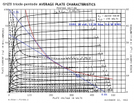
The attached image shows one of my attempts to figure out what transformer to use with a pair of oddball power valves (the valve type is in the image.) These particular valves are cheap, and include both a triode and a pentode in one envelope, so in principle one could build a complete guitar power amplifier using just two output tubes. No 12AX7's needed, except in the preamp!)Parts of this curve approach two notable resistances.
Because these are oddball valve types, nobody seems to have built a guitar amp using them, or if they did, no details made it to the Internet. So I had to figure out for myself what transformer would work with a pair of these in push-pull.
It would be very tricky (and unnecessarily accurate) to try and work out the actual shape of that curved load-line that PRR talked about. So to simplify things, I pretend the load-line is two straight lines (the two resistances PRR refers to above), meeting each other so as to create a sharp kink in the load-line. (In reality there won't be a kink, and one line will curve smoothly into the other.)
Based on my intended B+ voltage, the slope of the load line, and the valve's power dissipation rating, I chose to bias each output valve at 20 mA. If a positive half-wave guitar signal comes along and increases the current in one valve to, say, 30 mA (a 10 mA increase), and things are reasonably symmetrical, we can expect that the current in the other one decreases by roughly the same 10 mA, from 20 mA quiescent down to 10 mA.
So with an input signal of this size, both valves are in operation - one flowing 30 mA, the other flowing 10 mA - and the amplifier is still in class A.
This means current is flowing in both halves of the transformer primary. Each output valve now sees a load equal to one-half of the transformers end-to-end impedance. In my diagram, this equals 6.6k, as indicated on the lower half of the blue load-line.
However, if the signal gets bigger, and pushes current in one valve all the way up to 40 mA (an increase of 20 mA), we can reasonably expect that the other valve will experience a similar 20 mA drop in current - which will leave it flowing zero current. We've left class A behind, and are now in class B.
Because the second valve is no longer drawing any current, one half of the transformer primary is now doing nothing at all. As a result, the load impedance seen by the working valve is now one-quarter of the transformer primaries end-to-end value. This is 3.3k, as indicated near the top left corner of the load-line.
As you can see, our blue load-line has a kink in the middle, where it switches from the (higher) 6.6k load impedance seen in class A, to the lower 3.3k impedance seen in class B. For small signals, each output valve "sees" 6.6k, but that drops to 3.3k if the signal becomes big enough.
And what transformer should I buy? Well, manufacturers specify the end-to-end impedance, which is twice the class-A load of 6.6k. In other words, I need a transformer with an end-to-end primary impedance of 13.2k.
This isn't an off-the-shelf value, but 6.6k is. So when I was working out what might work with these particular output valves, in the back of my mind was the idea of a 6.6k OT, but with an 8 ohm speaker connected to the 4 ohm tap, to double the primary impedance to 13.2k.
Nothing is exact in this entire discussion; we're talking valves and guitar amps, so we won't even worry about little things like plus/minus twenty percent tolerance on anything.
I haven't actually built this (yet!), but I thought the process I went through to create the attached image might be helpful.
-Gnobuddy
Attachments
> I chose to bias each output valve at 20 mA.
Why? Yes, you need a bias eventually, but since you already expect/suspect you will have to drive it past class A to make big power, you don't need to have a bias to compute the FULL power conditions.
Plot from 330V zero current, up to "the knee". Yes, 3.3k is a fine fit. (3.5k might be insignificantly better, altho also off the chart.) So the OT will be sold as "13.3k CT", agree. (And yes, 6.6k misloaded 2:1 is easier to find.)
THEN consider bias. You can actually diddle bias while it plays, it's still the same amp. you can try to bias AT zero current, you can't, and if you did it would have big deadband. You can bias-up to the Pdiss line, rich AB. Or split the difference, like my cool AB. Because my 10mA cool AB is way down on Gm for small signals, I'd expect that to suck on soft sounds.
With the FULL ROAR and the idle sketched you can draw the dynamic loadline.
IF the tube Gm/Ip models as square-root, then there is a first order optimization when Ip(idle) is similar to 1/4 of Ip(peak). Here that says 25mA. Which does fall right on Pdiss. And may be safe. The optimization is not critical or exact, so trimming to 20mA seems perfectly reasonable too. This may be deferred to final testing as first-crack and down-the-road as you observe lifetime tube replacement costs.
Attachments
It didn't dawn on me to start with the class B loadline first. Thanks for that idea!Why? Yes, you need a bias eventually...
That image was produced after a few tries, and so incorporates some practical features such as a B+ voltage readily obtained with a 240V:120V AC isolation transformer wired backwards, and an off-the-shelf OT.
Tubelab George seems to use pretty cool bias in many of his experimental PP guitar amps, usually along with unusually large B+ voltage, and then somehow repeatedly ends up wringing 30 RMS watts or more from a pair of $1 valves without over-dissipating anything.Because my 10mA cool AB is way down on Gm for small signals, I'd expect that to suck on soft sounds.
Cool bias seems to work for him, but I have a feeling that "soft sounds" might not be on George's guitar-playing agenda.
Interesting, that sounds like a useful result.there is a first order optimization when Ip(idle) is similar to 1/4 of Ip(peak).
It might have enough safety margin if I drop B+ a bit, sliding the load-line to the left in the process. Something to think about if/when I build it and see/hear how it behaves through the crossover.Here that says 25mA. Which does fall right on Pdiss.
At the initial planning stage, the main attractions for this amp are (1)$1 valves, (2)Only two bottles needed for both PI and output stages, (3)Cheap PT, twenty-two buck Triad N68X even with the weak Canadian dollar, and (4)Off-the-shelf 6.6k OT, one of which I happen to have sitting in my junk-box.
It remains to be seen if PI and output in the same bottle can be made stable or not. Mebbe cross-wire the triodes, so the pentode anode signal is out of phase with the triode input in the same glass envelope?
-Gnobuddy
- Status
- This old topic is closed. If you want to reopen this topic, contact a moderator using the "Report Post" button.
- Home
- Live Sound
- Instruments and Amps
- push-pull. input impedance in output transformers