I'm trying to make an old project of mine function after building it (badly) years ago. It was my first scratch-built point-to-point tube project, and I was not competent enough at the time. It's an Organ Mate add on reverb unit that I reconstructed with the old iron and mostly new components in a new chassis. I got so frustrated I put it away five or so years ago intending to try again some day.
I've run down a bunch of problems and have got it passing wet and dry signal. The reverb is nice and deep, but the gigantic 60-cycle hum is distracting! So, I'm troubleshooting and checking voltages as well as looking at grounds. I found 2 ground loops. Fixing them improved the hum, but not enough.
Anyway, all the voltages are about 10% too high. Is this because the unit was intended for 115v rather than 120v? The only exception is pin 1 of the 12AX7 tube -- it's at 190v rather than the specified 250v. If I measure at the plus side of the filter cap I get 265v, but after a 330k resistor, the voltage drops to 190v. If the high voltage is correct at the source, why do I need that resistor at all?
Thanks in advance for any assistance!
Attachments
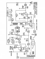
C7 (20uF) and R13 (330K) form the decoupling (smoothing) filter for that 12AX7 valve section.
Until the experts come in, have a read of this:
The Valve Wizard
Until the experts come in, have a read of this:
The Valve Wizard
Don't worry if your voltages are all off some, this is not lab equipment.
R13 is the plate load for the 12AX7 section.
"Wrong" voltages don't cause hum.
Hum is not generic, it comes from MANY places and each one has its own cure. Meaning More filter caps will have no effect on a ground loop, and new grounds won't improve failing filters.
Unplug the reverb pan and short across the return jack, ie ground pin 7 of the 12AX7. Hum remain?
Unplug the remote volume control, any help? In fact did the volume control control the loudness of the hum?\
Ground the input jack, hum go down?
Are the two 47 ohm resistors OK by the heaters? If you try to measure one, it will read half its value.
How much ripple is ther at C6? At C3?
Pull teh 12AU7, hum go away?
We are trying to isolate the source of your hum. And you may have more than one.
Get your reverb pan (the spring assembly) as far as possible from the power transformer, does that reduce the hum?
Hi Enzo, I did not unplug the reverb yet (it's hard wired to the circuit like the original). Ditto the volume control -- I made a new lead from 2 conductor shielded wire and soldered it in place. I will do these tomorrow.
Grounding the input jack does nothing, but pulling the 12AU7 killed the hum entirely. Does this mean the cause of the hum is associated with the 12AU7?
All the components in the circuit are new, including the filter caps.
I don't know how to measure ripple. I do have a 'scope but I don't know how to use it yet.
I did a good job on the heater runs, twisted and running around the margin of the chassis. I'd post a pic, but A. it's an embarrassing mess in there, and B. the chassis is so effing small (4" x 6") you wouldn't be able to see anything. Both the original chassis and my reworked one mount directly to the top of the reverb tank!
Moving the chassis away from the tank made the hum much worse. They're grounded together. I tried moving it away while maintaining the ground connection, but even gentle movement of the tank & chassis causes massive crackling and hum. Nothing's loose inside to cause this. Any ideas? I also tried disconnecting the volume control, but no joy. And yes, the pot increases the hum as it turns. It's the wet/dry control. Does this mean my tank is defective?
Likely, yes.Grounding the input jack does nothing, but pulling the 12AU7 killed the hum entirely. Does this mean the cause of the hum is associated with the 12AU7?
Grounding the input did nothing, so the hum isn't coming in from a previous stage. Removing the 12AU7 stops the hum, so it's most likely not being generated in the reverb tank wiring. (This is not 100% certain, because when you unplug the 12AU7, you also stop drawing heater current to it - and that heater current right on top of your reverb tank might actually be the cause of the hum.)
Enzo suggested you measure power supply ripple because that is one possible source of hum from the 12AU7. If you don't know how to do that, I suggest getting a new, known good electrolytic cap - say 47 uF - rated for 400 or 450V DC, and tack-soldering it in parallel with first C5, then C3 to see if the hum changes.
If the hum drops dramatically when the cap is added, the existing filter cap (C5 or C3) is not doing it's job and needs to be replaced.)
One other thing you can try is to tack-solder your 47 uF cap in parallel with R6 (330k). Did the hum go away? (This will help to answer whether the hum is caused by the 12AU7 heater current near the reverb tank.)
In all cases, make sure to check and double check the polarity of your added cap. And make sure you unplug the circuit and fully discharge all power supply filter caps - double check with a DMM that there is no DC voltage across C3, C5, C6, C7, before trying to tack-solder your new cap in place.
What kind of scope do you have?I do have a 'scope but I don't know how to use it yet.
You may already now this - many scopes can be damaged if you try to measure hundreds of volts with them. Of course valve circuitry routinely has hundreds of volts in many places, so this poses a risk to your 'scope.
One way to avoid this danger is to use the right type of 'scope probes. Known as "x100" probes, these divide down the incoming signal a hundred times, lowering it to a safe voltage, before feeding it to the 'scope.
But you have to remember to multiply your 'scope readings by 100 to get the right answer: if the 'scope shows 2.5 volts, you actually have 250 volts, and so on.
In the meantime, you can safely experiment with your scope by trying to observe the voltage from the 6.3V heater windings. That's low enough to be safe for any scope. Try setting it to 1 or 2 volts per division (vertical), and 10 mS/div horizontal. Ground the 'scope probe wire, clip the tip of the probe to pin 4, 5, or 9 of either tube. That should be enough to see something, and you can fine-tune the settings from there.
If you have a modern 'scope, it will often have an "Auto" button that magically figures out the right settings needed to display your waveform. Just connect the probe (ground and either pin 4, 5, or 9), then push the button.
You do still have to select the correct channel, and attach the probe to the right input jack, though.
-Gnobuddy
....filter cap I get 265v, but after a 330k resistor, the voltage drops to 190v. If the high voltage is correct at the source, why do I need that resistor at all?....
There's no "right voltage". Tubes hardly care.
Likewise 330k or 400k is no big deal.
If you did not have the 330k resistor, your signal output would be the top of the *filter cap*. Which is ideally dead silent!!
One tube can not work alone. It either needs another tube (complicated) or some passive part to "fight against". The 12AX7 can be grid-driven from about 60k to >1,000k. If we team it with a 330k resistor we have "a fair fight". The tube can pull down, or turn-off and let the resistor pull-up.
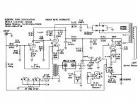
That is a TERRIBLE drawing. A less-experienced builder is likely to get many things wrong, especially ground plan. Post a clear picture of what you built. Maybe we'll see some key change. Maybe we'll tell you to rip much of it out and do it again, right.
Attachments
Gnobuddy, you asked about my scope. It's an old B&K 1460. I had a friend who knows a lot about scopes test it, and it's functional. Wiseoldtech, yeah my grounding scheme sucks. I've built a few tube amps, and I always do a star ground, but I put this reverb together before I knew about such things. There must be 5 or 6 separate ground points! I'm about to try a bunch of the suggestions above. I'll report back later today.
I agree. Surely one of the worst-drawn schematics I've ever seen in my life. Whoever drew that should be forced to listen to "The Lion Sleeps Tonight" one hundred times in succession, with no pauses.That is a TERRIBLE drawing.
-Gnobuddy
Ah. On the minus side, there won't be an "Auto" button that automatically sets everything correctly to display a waveform. On the plus side, an old valve (tube) 'scope like this will probably cope better with the high voltages in your tube circuit once you figure out how to use it....It's an old B&K 1460...
As Enzo pointed out, hum problems are harder to track down than many other types of circuit misbehaviour, because there are so many different possible causes. In this case, it seems you already know of one major cause......my grounding scheme sucks....There must be 5 or 6 separate ground points...
That certainly suggests a course of action to try and solve your hum problem, doesn't it? If you already know the toilet's overflowing and there's sewage all over the bathroom floor, maybe there isn't much point to first checking if last night's unwashed dinner-plates are the source of that unpleasant smell?
-Gnobuddy
Hi all! I'm going to bite the bullet and start over with a bigger chassis. I have one last favor to ask for now: most of you commented on how terrible the schematic is. Are you criticizing the actual drawing or the circuit? Are there particular problem areas? Would you guys be willing to mark up the attached copy to fix the mistakes? TYTY!
I missed this one earlier. There are two coils (wire) inside your reverb tank, one connected to the input of the reverb tank, the other to the output.Does this mean my tank is defective?
You can use your DMM set to measure ohms to test these internal coils for electrical continuity. Measure between centre and shield of the RCA jacks.
If both coils measure something reasonable, it's unlikely the reverb tank is causing your hum. (The tank could still be defective in the sense that the reverb might not work.)
-Gnobuddy
The actual drawing.Are you criticizing the actual drawing or the circuit?
Yes, pretty much the entire upper half of the schematic!Are there particular problem areas?
The way it's drawn, it's difficult to tell which components are part of the power supply, and which are part of the four triode stages. A well-drawn schematic diagram is laid out in a way that makes it easy to understand what each component is doing.
This particular schematic is the opposite - it looks like something the cat threw up, logically speaking. Electrically correct, but a visual mess, as though auto-generated by Fritzing (which does spectacularly bad PCB design.) The original draughtsman did a terrible job.
It really wants re-drawing...if I can find the time, I'll try, but my life is very busy this week, with a lot of minor fires that all need putting out in a hurry.Would you guys be willing to mark up the attached copy to fix the mistakes? TYTY!
-Gnobuddy
- Status
- This old topic is closed. If you want to reopen this topic, contact a moderator using the "Report Post" button.
- Home
- Live Sound
- Instruments and Amps
- Tube Noob Voltage Question