Thank you for all your input.
Thanks.
The 10k pot cuts off all sound when I turn it down all the way. I suppose that might change if the final power supply is 12V or 15V DC instead of 9V. However, assuming that a 10k pot is sufficient for silence when turned down all the way, why should the pot be changed to 25k? Would that create a large silence zone when the pot is below, say, 7 or 5 (or whatever) out of 10?
I tied pin 7 to ground with a 10k resistor and 10uF cap in between. I didn't notice any change.
I'm going to do that with a 10k pot before the cap, so that I can adjust gain. Since the gain can't go below 20, would a 10k pot here?
In your mark-up of the schematic, you changed the initial signal input from pin 3 to pin 2. Why? Pin 2 is for inverting (-) input; pin 3, for non-inverting (+). Isn't the inout from the guitar jack non-inverting? Although I did see some schematics feeding the signal into pin 2, most of the schematics out there feed the signal to pin 3.
The R-C on the '386 output is critical for stability, and must be 10 ohms (not 10k).
Thanks.
Try a better volume pot connection and value.
The 10k pot cuts off all sound when I turn it down all the way. I suppose that might change if the final power supply is 12V or 15V DC instead of 9V. However, assuming that a 10k pot is sufficient for silence when turned down all the way, why should the pot be changed to 25k? Would that create a large silence zone when the pot is below, say, 7 or 5 (or whatever) out of 10?
You should really have a cap on pin 7, to reduce supply crap and set-up the internal gain structure properly.
I tied pin 7 to ground with a 10k resistor and 10uF cap in between. I didn't notice any change.
A cap on pins 1 and 8 will make a WOW! difference of gain. But also begs for squealing in haywire builds. 500 to 200 ohms in series with this cap gets intermediate gains.
I'm going to do that with a 10k pot before the cap, so that I can adjust gain. Since the gain can't go below 20, would a 10k pot here?
In your mark-up of the schematic, you changed the initial signal input from pin 3 to pin 2. Why? Pin 2 is for inverting (-) input; pin 3, for non-inverting (+). Isn't the inout from the guitar jack non-inverting? Although I did see some schematics feeding the signal into pin 2, most of the schematics out there feed the signal to pin 3.
Last edited:
My last builds with it, only thing that would stop it was a 2.2uF ceramic cap right across the IC's power pins.
I'm not sure what you mean by "power pins" because the LM386/NTE823 has only power input at pin 6 (V+) - unlike the LM3886, which is most commonly built with V+ and V-. Do you mean that a 2.2uF ceramic cap should be put across pins 6 (Vs) and pin 4 (ground)?
edit: you also need bulk cpacitance like 220uF across power
Following advice at the Circuit Basics site, I put a 100uF cap across the + and - lines out of the battery, with a 1uF cap across those lines a little further downstream. The larger cap is supposed to filter out low frequencies; the smaller cap, high frequencies. (A 0.1uF cap was recommended for the latter, but a 1uF cap was the closest I had on hand.) I do not connect the ground wire from the battery to the - rail on the breadboard edge until after these 2 caps. Also, the only place to which the + wire is attached after these 2 caps is pin 6; the + wire is not connected to the breadboard edge rails. In any event, what do you think of this 2 cap approach for different frequencies?
Last edited:
A guitar puts out a very small signal and usually needs a pre amp before the amplifier.
The Danalectro Billionaire ("Texas Trouble") pedal is powered by a 9V wall wart and appears to function as a pre-amp.
Are you sure the amplifier has enough gain?
With the default gain of 20 built into the chip, the amp is too weak to hear the guitar. Even turning the guitar gain knobs makes no difference. It remains to be seen whether the amp will have enough gain without the stomp box after I add a pot and cap between pins 1 and 8, so that I can raise the gain incrementally up to 200. In the meantime, I have to use the stomp box as a preamp if I want to hear the guitar thru this chipamp.
As noted several times above, I need to use a stomp box as a de facto preamp or else this amp does not have sufficient volume to hear the guitar. The stomp box is powered by a 9V wall wart. It occurred to me that this wall wart probably "infects" the guitar signal in from the guitar jack. From the guitar jack, the signal goes thru the pot and from there to pin 3 (maybe, later, to pin 2 if it can be explained to me why pin 2 is more appropriate than pin 3). There currently is no cap between the guitar jack and pin 3. Should I add a cap between the pot and pin 3? With the same specs/rating as used between the 9V battery and pin 6?
> The 10k pot cuts off all sound when I turn it down all the way.
So? If all sound is cut off, why do you have an amplifier?
In this case it cuts-off because it SHORTS the signal source. This is usually unwise.
If you flip top and wiper, it will still cut-off but the signal source sees a fairly constant 10k.
However 10K is VERY low for guitar-cord work. And I didn't suggest 25k but 250k. We would like >500k for guitar, but are compromised by the 50k input of the LM386. 250k is a fair fit.
In any case the LM386 alone is not a good guitar amp. Look for "Ruby Amp", which is a '386 plus a buffer. There are even better plans around.
Let me start by saying I commend your enthusiasm, and wish you luck. You have a long road ahead of you if you stick with it, but you can have a lot of fun along the way.
Using a 250k pot here instead of a 10k pot will slightly "soften" the volume response as you turn the pot up from zero. Depending on other factors, this might feel like an improvement.
Changing the pot isn't the first change I'd suggest, however. Fix the worst problem first...and the worst problem is using a breadboard with a high-bandwidth analog chip amp. It is a recipe for creating a radio-frequency oscillator rather than an amplifier.
The problem is that under the surface, a breadboard is a huge collection of closely-spaced parallel wires, each half an inch or so long. There is a stray capacitance in between every two wires. In effect, any circuit you build on a breadboard has a random small-value capacitor connected between every two pins you plug in.
Some circuits will tolerate this, but usually only if they are either slow, or have little gain, or have low input impedances, or all of the above. Build a Fuzz-Face with a couple of ancient, slow, germanium transistors on a breadboard, and you won't have any problems.
But when you put a fast circuit with high input impedance and high internal gain on a breadboard, the results are usually ugly. Usually, you just get a wildly unstable, very noisy, utterly unusable result. Integrated power amplifiers tend to be particularly prone to instability even with careful design and construction, and a breadboard is pretty much the opposite of "careful design and construction."
Do you know how to solder? If not, it's time to learn. And once you feel comfortable that you can solder to a tiny chip without damaging it, build your LM386 amp on a little piece of proto-board, a general purpose PCB. Pick one that doesn't have dozens of parallel, closely spaced conductors - otherwise it'll be back to building an unintentional short wave radio transmitter.
This cap will reduce hum IF the hum is caused by AC ripple on the power supply for the LM386. It will do nothing to reduce hum caused by poor layout, poor grounding, and having a breadboard lying out in the open, picking up stray electrical interference from everything.
Does your power supply (wall-wart) have only two pins that plug into the AC outlet? Then your amp isn't grounded at all, except through your hands when you touch the guitar strings. This makes the amp hum until the guitar is touched, even if all the circuitry is properly shielded inside a metal housing. (Your circuitry is out in the open, unshielded, a sitting duck for all the electrical noise flying through the air.)
I recently re-discovered a free resource that I think will be very helpful to you. The first few chapters of this book will answer a *lot* of the questions you're asking, and teach you a lot of things you haven't yet realized you don't know. Here you go: https://www.msu.edu/~dougl126/Electronic Projects for Musicians.pdf
Good luck!
-Gnobuddy
No, it will still cut off all sound when set to zero. Google and study "voltage divider", and then "volume control".The 10k pot cuts off all sound when I turn it down all the way. I suppose that might change if the final power supply is 12V or 15V DC instead of 9V.
PRR suggested 250k (not 25k). The intention was to raise the input impedance of your LM386 amp, making it easier to drive directly with an electric guitar. However, you're using a guitar pedal in between guitar and LM386, so you won't gain anything by this; you can keep the 10k log pot....assuming that a 10k pot is sufficient for silence when turned down all the way, why should the pot be changed to 25k?
Would that create a large silence zone when the pot is below, say, 7 or 5 (or whatever) out of 10?
Using a 250k pot here instead of a 10k pot will slightly "soften" the volume response as you turn the pot up from zero. Depending on other factors, this might feel like an improvement.
Changing the pot isn't the first change I'd suggest, however. Fix the worst problem first...and the worst problem is using a breadboard with a high-bandwidth analog chip amp. It is a recipe for creating a radio-frequency oscillator rather than an amplifier.
The problem is that under the surface, a breadboard is a huge collection of closely-spaced parallel wires, each half an inch or so long. There is a stray capacitance in between every two wires. In effect, any circuit you build on a breadboard has a random small-value capacitor connected between every two pins you plug in.
Some circuits will tolerate this, but usually only if they are either slow, or have little gain, or have low input impedances, or all of the above. Build a Fuzz-Face with a couple of ancient, slow, germanium transistors on a breadboard, and you won't have any problems.
But when you put a fast circuit with high input impedance and high internal gain on a breadboard, the results are usually ugly. Usually, you just get a wildly unstable, very noisy, utterly unusable result. Integrated power amplifiers tend to be particularly prone to instability even with careful design and construction, and a breadboard is pretty much the opposite of "careful design and construction."
Do you know how to solder? If not, it's time to learn. And once you feel comfortable that you can solder to a tiny chip without damaging it, build your LM386 amp on a little piece of proto-board, a general purpose PCB. Pick one that doesn't have dozens of parallel, closely spaced conductors - otherwise it'll be back to building an unintentional short wave radio transmitter.
Remove the 10k resistor. The cap should go directly from pin 7 to ground.I tied pin 7 to ground with a 10k resistor and 10uF cap in between. I didn't notice any change.
This cap will reduce hum IF the hum is caused by AC ripple on the power supply for the LM386. It will do nothing to reduce hum caused by poor layout, poor grounding, and having a breadboard lying out in the open, picking up stray electrical interference from everything.
Does your power supply (wall-wart) have only two pins that plug into the AC outlet? Then your amp isn't grounded at all, except through your hands when you touch the guitar strings. This makes the amp hum until the guitar is touched, even if all the circuitry is properly shielded inside a metal housing. (Your circuitry is out in the open, unshielded, a sitting duck for all the electrical noise flying through the air.)
You've mis-read PRR's sketch. Look closer - the guitar signal goes through the volume pot, to pin 3. And pin 2 goes to ground (that's what the arrow-head symbol means - ground.)In your mark-up of the schematic, you changed the initial signal input from pin 3 to pin 2.
I recently re-discovered a free resource that I think will be very helpful to you. The first few chapters of this book will answer a *lot* of the questions you're asking, and teach you a lot of things you haven't yet realized you don't know. Here you go: https://www.msu.edu/~dougl126/Electronic Projects for Musicians.pdf
Good luck!
-Gnobuddy
No, it will still cut off all sound when set to zero. Google and study "voltage divider", and then "volume control".
Using a 250k pot here instead of a 10k pot will slightly "soften" the volume response as you turn the pot up from zero. Depending on other factors, this might feel like an improvement.
I guess I misunderstand how a pot works. I read that a pot is essentially a variable resistor, with 0 of 10 being the maximum rated resistance and 10 being zero resistance. With the current linear 10k pot (the package said "no switch," IIRC), there is no sound. Isn't that because the maximum rated resistance of 10K ohms is sufficient to silence the audio output, and not because zero is an off switch? If so, then substituting a linear 250k pot would make 0 a resistance of 250K, no? And since, with a linear pot, everything below approx. 9.6 of 10 would be > 10K resistance and 10K is sufficient for silence, doesn't that mean that 0 to 9.6 would be silence and the entire range of available sound would be confined to the knob range of approx. 9.6 to 10? I need more granularity than that in tweaking volume.
Fix the worst problem first...and the worst problem is using a breadboard with a high-bandwidth analog chip amp. It is a recipe for creating a radio-frequency oscillator rather than an amplifier.
I'll have to do that after I get all the pieces of the puzzle together in one place first. It would be too confusing to move everthing over just now, with this first project.
Do you know how to solder? If not, it's time to learn. And once you feel comfortable that you can solder to a tiny chip without damaging it, build your LM386 amp on a little piece of proto-board, a general purpose PCB. Pick one that doesn't have dozens of parallel, closely spaced conductors - otherwise it'll be back to building an unintentional short wave radio transmitter.
I learned to do oxy-acetaline and electric arc welding in shop class way back in the 1970s. Soldering has not been as difficult as I expected. I could use a better iron that heats up faster, but that can wait. In any event, I don't see myself doing any surface-mount soldering with microscopic components. Only through-hole.
I ordered a bunch of PCBs that have holes with metallic rings on both sides but no connection between any of the holes. The holes are pretty close together; I'll have to practice on those. If I have too much trouble with those boards, I will use phenolic boards or others that have no conductive materials on or in them.
Remove the 10k resistor. The cap should go directly from pin 7 to ground.
Done. I don't notice a difference, but I appreciate that ground lines should always be the shortest and fastest route to ground.
Does your power supply (wall-wart) have only two pins that plug into the AC outlet? Then your amp isn't grounded at all, except through your hands when you touch the guitar strings.
For now, I am using a 9V battery for amp power. Two lines there. For the guitar, I am using the stomp box and its 2-prong wall wart. I'll keep in mind your point about needing a separate ground (apart from the neutral or return, which goes back to the same bus on the side of my house as ground wires do). Hmmm, I should check whether the Fuzz-Face or other stomp boxes are built with a separate ground.
You've mis-read PRR's sketch. Look closer - the guitar signal goes through the volume pot, to pin 3. And pin 2 goes to ground (that's what the arrow-head symbol means - ground.)
I misspoke. I'm confused. His notations changed which guitar jack lines go to which which pins on the pot (rather than the chip). I got the pot pin wiring from How to Wire a Potentiometer: 10 Steps (with Pictures) - wikiHow I'll have to double-check that I followed those instructions correctly.
I recently re-discovered a free resource that I think will be very helpful to you. The first few chapters of this book will answer a *lot* of the questions you're asking, and teach you a lot of things you haven't yet realized you don't know. Here you go: https://www.msu.edu/~dougl126/Electronic Projects for Musicians.pdf
Thank you for that great resource! And thanks for all your other pointers, too.
Last edited:
You have some misunderstanding between pot value and pot ratio. I suspect Gnobuddy's link leads to better understanding.
A rough selection of Google images for Volume Control.
Some are Stereo, so only look at half. One has extra stuff, you don't need that here. One is duplicated (oops). There ARE times when your "backward connection" IS better; this is not one of them. Confirmed by the fact I did not find any backward-connected volume pots in hundreds of images.
Attachments
Last edited:
Not a variable resistor, but a voltage divider. Here you go: Voltage Dividers - learn.sparkfun.comI guess I misunderstand how a pot works.
Note the crucial point: it's the ratio of the two resistors that decides how much of the input signal appears at the output. In principle, R1=9k and R2=1k produces exactly the same result as R1=90k, R2=10k, or R1=225k, R2=25k. Each of these corresponds to a potentiometer set to one-tenth resistance; the potentiometers in the three examples are 10k, 100k, and 250k pots respectively.
In practice, other factors enter if we use utterly ridiculous potentiometer values; a one-ohm pot wouldn't work well in this circuit, nor would a hundred million ohm pot.
I understand the appeal of a breadboard. But it comes with some limitations, too. If you can get your circuit to work properly on the breadboard (without lots of hum, buzz, or bursting into radio-frequency oscillation), perfect.I'll have to do that after I get all the pieces of the puzzle together in one place first.
But if the amp never works right, because the breadboard prevents it from working properly, then you won't be able to make any progress, and in that case, its time to head for the protoboard instead.
Protoboards and chip amps don't get along all that well, either, by the way...a properly designed PCB is virtually mandatory with more powerful chip amps. Most of the time, the manufacturer includes a reference PCB design in the datasheet, and you make changes to it at your peril. The manufacturer may have had to put in a lot of effort to design a PCB that keeps the chip amp stable and audio distortion low.
It's a lot less dangerous than welding, and that makes it easier to learn - you don't have to take the same level of precautions, or wear bulky and awkward protective gear. All it takes is a little practice, until your hands and brain figure out what works well, and what doesn't.Soldering has not been as difficult as I expected.
So far I've avoided SMD stuff, too. The thing is, through-hole is a dying technology, and available choices will continue to diminish with every passing year. For instance, most of the current crop of cheap, good-quality class D chip amps are only available in SMD packages. So I don't DIY today's chip amps...I buy pre-made amp boards from Amazon or Ebay.I don't see myself doing any surface-mount soldering with microscopic components. Only through-hole.
True. In this particular case, it's the 10k resistor you really don't want - the idea of the bypass cap is to provide a low-resistance path to ground for AC signals (hum, noise, ripple), while not having any effect at all on the DC voltage at pin 7.Done. I don't notice a difference, but I appreciate that ground lines should always be the shortest and fastest route to ground.
Remember how a volume control is a voltage divider? Remember that a voltage divider is two resistors in series? Here's a little extension of that idea: a resistor (the 15k one between pin 6 and pin 7 of the LM386) and a capacitor (the bypass cap from pin 7 to ground) can also form a voltage divider - but only for AC voltages, not DC voltages. (Google "capacitive reactance" and "RC low pass filter" for more information.)
Good idea! That'll eliminate one source of hum and noise for now.For now, I am using a 9V battery for amp power.
Try placing the breadboard in or on some sort of metal housing, and ground that housing to the negative terminal of the 9V battery. A square of aluminium kitchen-foil will work in a pinch, or a metal baking tray or cookie sheet. This will reduce hum and noise picked up out of thin air.
Every two-prong wall wart I've seen has a fully isolated secondary: neither of the DC output wires connects back to either of the incoming AC wires. This is really the only way to avoid shocking or electrocuting the user 50% of the time, if you stop and think about it!Two lines there. For the guitar, I am using the stomp box and its 2-prong wall wart.
Worse, most of the time, the DC output side of the wall wart is connected to the AC "hot" wire by a small capacitor, and also connected to the AC neutral by a second small capacitor. This means the output (DC) ground is usually floating at about 80 volts AC, constantly fluctuating, reversing polarity 120 times a second in North America. Very different from the constant zero volts we'd like for a ground wire!
Since the wall-wart output isn't grounded, and neither is your 9V battery, this means your guitar FX pedal probably has no grounding at all, and neither does your chip amp. Can you say "Hum and buzz"?
If the hum quiets down when you touch the guitar strings, it confirms this. Your body is acting as a (poor quality) ground.
You're very welcome.Thank you for that great resource! And thanks for all your other pointers, too.
-Gnobuddy
Google images for Volume Control.
Thank you very much.
I need to revisit the last few posts with a refreshed mind tomorrow. In the meantime, the attached mp3 captures a weird sound from my work in progress when the amp is toggled off while the stomp box is on. The toggle click can be heard right before the weird sound. Is that the sound of a cap discharging? You might have to turn the volume up.
Attachments
how to wire up a volume control. So I made the attached image to clarify how it's done.
Is that from the bottom, with the wiper shaft on the other side?
Mine is not wired that way now, but the amp is working, albeit noisily. If it's wired incorrectly, shouldn't the pot not work at all?
Last edited:
Hey guys, you are running circles around a TROLL
Just a few samples, there´s dozens more:
When asked about his soldering skills:
And nobody reacts to this nonsense? Oh well ...
Fck´n unbelievable.
Yet respected Forum Members WASTE time here.
And so on and on and on.
Did anybody notice the input is NOT referenced to ground but insulated by a capacitor?
Which would explain the >8V DC present there and the stuck-to-+V speaker out, which apparently didn´t bother anybody.
In my book, FIRST get DC voltages right, THEN worry about sound, oscillation or whatever.
Here:
Ok, it´s your time, I guess "helping" a Troll is better than watching the 24/7 Commercials Channel or whatever.
Just a few samples, there´s dozens more:
When asked about his soldering skills:
Yea, sure, that will help a lot.I learned to do oxy-acetaline and electric arc welding in shop class way back in the 1970s.
Try to make solder stick straight to epoxy fiberglass or phenolic, no metals involved, that will also help a lotI ordered a bunch of PCBs that have holes with metallic rings on both sides but no connection between any of the holes. The holes are pretty close together; I'll have to practice on those. If I have too much trouble with those boards, I will use phenolic boards or others that have no conductive materials on or in them.
So you measure with probes NOT touching the circuit?When I use my MM to test voltage, the numbers are all over the place and usually drop to zero after a split second. I have to take the leads off and wait a bit before getting significant numbers.
And nobody reacts to this nonsense? Oh well ...
And it took you how many hours/days to notice that?It turns out that all my 9V batteries were dead
Fck´n unbelievable.
Yet respected Forum Members WASTE time here.
Proper voltages are 0 (as in ZERO) and around 6V, but if what you measure is "good" then why complain?I re-attached the 12V DC PSU from a dead disc player. With these changes, I read 8.26V DC at pin 3 (audio input) of the NTE823 chip and 11.07V DC on pin 5 (audio output to the speaker). So far, for my purposes, so good.
And so on and on and on.
Did anybody notice the input is NOT referenced to ground but insulated by a capacitor?
Which would explain the >8V DC present there and the stuck-to-+V speaker out, which apparently didn´t bother anybody.
In my book, FIRST get DC voltages right, THEN worry about sound, oscillation or whatever.
Here:
14 answers later, nobody even noticed that GROSS error.To simplify things for troubleshooting, I temporarily removed the pot from the breadboard and now run the audio in thru a 4.7K 1/2W resistor and a 0.033uF 100V cap to the audio in pin (pin 3). The idea (remember, I'm a total noob) is to replace the pot with the equivalent of setting the volume pot to 5 out of 10 but without potential mistakes wiring the pot between the 1/4" jack and the chip. With this simpler setup, I read 8.26V DC on pin 3 (audio in), immediately behind this resistor and cap.
Ok, it´s your time, I guess "helping" a Troll is better than watching the 24/7 Commercials Channel or whatever.
Well, I don't see this the same way you do. I think we're seeing early, stumbling steps.
I started tinkering with electronics when I was very young, and my early experiences weren't all that different. Loose connections, intermittent connections, et cetera.
When I was still a boy I've also built circuits on cardboard (the covers of last year's school notebooks!), thin plywood, and bare phenolic board, because that's what I found lying around, and I had no money to buy anything more suitable; I just bent the component's own wire leads over underneath the cardboard and used them as PCB traces, or added short lengths of wire as necessary.
Ultimately, how we view this is a matter of viewpoint. I'd rather give someone the benefit of the doubt; I'd rather make the mistake of trying to help someone who doesn't really want help, than make the mistake of dismissing someone who is being sincere as a troll. A wise older friend once said to me "There are three rules to living a good life; kindness, kindness, and kindness."
Oversimplification, perhaps, but I think there's a great deal of truth in that.
As you said, it's not as though there's some great loss to be incurred because of spending an hour trying to help someone else; I would probably have wasted that hour watching something on NetFlix otherwise.
-Gnobuddy
I remember the LM386 as an apprentice electronics engineer in 1980.
The whole class built one each.
Pretty much everyones oscillated and over heated and that was on a home built pcb.
It needs decoupling well closely to work right.
With those chip amp's they also need a very tight feedback resistor path.
The whole class built one each.
Pretty much everyones oscillated and over heated and that was on a home built pcb.
It needs decoupling well closely to work right.
With those chip amp's they also need a very tight feedback resistor path.
Hey guys, you are running circles around a TROLL
You really think a troll would put as much effort into trying to explain and to ask intelligible questions as I do? I'm a 59YO total noob, not a troll. And most of your quotes do not identify nonsense but rather my still imprecise use of this new language and omission of words assumed to be obviously implied. I'll illustrate with your first 2 examples.
Just a few samples, there´s dozens more:
When asked about his soldering skills:
Yea, sure, that will help a lot.
D
Oxy-acetalene (sp? it's been a long time) involves using a heating tool in one hand and a rod in the other to melt the rod onto/into the heated joint. The electric arc process (perhaps called something else 45 years later) combines the heater and the rod to melt the rod and joint together while unable to see how hot the joint is and trying to avoid making oneself part of the circuit. You don't see parallels? I do. That's why what little soldering I've done up to this point (only guitar jacks and pots because I got tired of alligator clips falling off repeatedly) has been fairly easy.
Try to make solder stick straight to epoxy fiberglass or phenolic, no metals involved, that will also help a lot
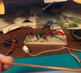
Put pins thru holes. Twist pins on bottom side. Solder twisted joint. Snip excess off. Where a conductive run is needed, use piece of insulated wire or, in case of the main ground, bare copper, such as the bare copper ground wire taken from a piece of 12/3 Romex. and shown(at the bottom) in the attached photo. And, oh, that's my actual project in the background (and, yes, I'm aware that something - a pot to control gain - is missing between the green wires, on their left ends).
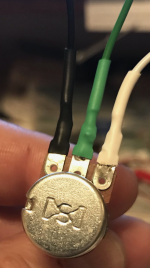
As for that pot, I believe I wired it correctly in the attached photo (black is ground, white is signal in, and green is signal out), thanks to the kind advice of others in this thread.
So you measure with probes NOT touching the circuit?
And nobody reacts to this nonsense? Oh well ...D
Me: "*I have to take the leads off and wait a bit* before getting significant numbers."
It should have been obvious that what I meant was taking the leads off and waiting a bit for the display to clear before I took another reading, i.e. by re-placing the leads on and getting significant numbers. As I said, it should have been obvious.
And it took you how many hours/days to notice that?
Fck´n unbelievable.
That was re: dead 9V batteries. I made no secret of the fact that I moved over to the 12V PSU salvaged from a dead Sony DVD/BlueRay player. Since this was supplying power into the project, I was in no rush to buy new 9V batteries. When I eventually did buy new batteries, I finally had something to compare the old batteries to and discovered the old ones were dead. Until I had the new ones for comparison, I found it hard to believe that the ENTIRE BOX of old batteries was dead. Remember, as I learn to build this very first electrical project, I am also learning things like how to use a multimeter and am not terribly confident in my ability to use it correctly.
Every other quote likewise can be explained or clarified easily. Do us both a favor and add me to your twitlist, now. I took the time to respond to your first 2 examples for those who have been kind enough to offer assistance. I'm not putting you on my twitlist because I've seen many good faith posts by you.
Attachments
Last edited:
In my book, FIRST get DC voltages right, THEN worry about sound, oscillation or whatever.
Please provide a link to your book.
If the hum quiets down when you touch the guitar strings, it confirms this.
No change when I touch the strings. Given what you said about breadboards, I'm resigned to a lot of noise until I move the project to an assembly board of some kind. I'm toying with the idea of using something untraditional and well insulated/isolated, as you did when you were a kid. (I seem to be approaching a second childhood of sorts.)
- Status
- This old topic is closed. If you want to reopen this topic, contact a moderator using the "Report Post" button.
- Home
- Live Sound
- Instruments and Amps
- Why does this LM386 breadboard not work as a guitar amp?