I'm an electronics noob (and beginner at guitar). Although I have a Marshall CODE50 - an SS combo amp with amazing abilities to emulate a lot of Marshall products from the past - I want something that is lighter and not so loud sometimes. I've decided to stick my toe in with a simple LM386 amp.
I can read simple schematics (5 years of shop in HS) and find soldering easy enough (having learned to do O/A & electric arc welding in HS). I have tried several very simple LM386 designs with no success, using a 9V battery supply or 12 DCV power supply from a Sony BlueRay/DVD player. My most recent attempt used this version - https://www.instructables.com/id/Know-Your-IC-LM386/ - because it is the first I have found with detailed wiring of the 10K linear pot used for volume. However, I get absolutely no sound from any version tried; not even a buzz, hum, snap, crackle, pop. I'll stick to the latest version for this post.
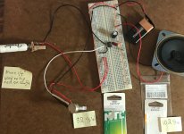
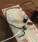
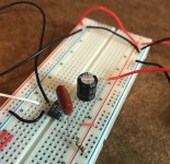
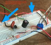
The details are shown in the attached photos. This thing is very simple. Apart from the 10K linear volume pot and the mono 1/4" jack for the guitar plug, it uses only an NTE823 chip (apparently identical to an LM386), a 220uF 50V cap, a 0.047uF 100V cap, and a 10ohm 1/4W resistor. The speaker is 8ohm 1/2W.
When I use my MM to test voltage, the numbers are all over the place and usually drop to zero after a split second. I have to take the leads off and wait a bit before getting significant numbers. My guess is that I'm discharging a cap or 2 when I touch + and ground, but that's just a guess. Two things that I know for sure are that (1) with the pot "ON" all the way, I see varying measurements of 5V, 8V, 10+V, etc. measured on the back leg of the 220uF cap, promptly dropping to zero; and (2) with the pot "OFF" all the way, I see about 0.050V, constant, measured on the back leg of the 220uF cap.
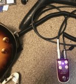
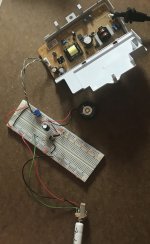
I have been trying to get amp sound out of my Les Paul electric, which has passive pickups in parallel and uses a 9V battery to deliver a 15db boost with one of the knobs pulled up. I have also added a Danelectro Billionaire (Texas Trouble) stompbox using a 9V wallwart. I hear a volume increase on my Marshall when I use the 15db boost and also when I use the stompbox. Even using both with the breadboard, I hear absolutely nothing come from the speaker. The MM readings in the preceding paragraph are taken with both the 15db boost and the stompbox ON. One of the attached photos shows the stompbox, FWIW.
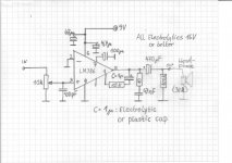
The pin layout of the NTE823 and LM386 are the same. The NTE823 specs are attached.
Any help would be greatly appreciated.
Jim
I can read simple schematics (5 years of shop in HS) and find soldering easy enough (having learned to do O/A & electric arc welding in HS). I have tried several very simple LM386 designs with no success, using a 9V battery supply or 12 DCV power supply from a Sony BlueRay/DVD player. My most recent attempt used this version - https://www.instructables.com/id/Know-Your-IC-LM386/ - because it is the first I have found with detailed wiring of the 10K linear pot used for volume. However, I get absolutely no sound from any version tried; not even a buzz, hum, snap, crackle, pop. I'll stick to the latest version for this post.
The details are shown in the attached photos. This thing is very simple. Apart from the 10K linear volume pot and the mono 1/4" jack for the guitar plug, it uses only an NTE823 chip (apparently identical to an LM386), a 220uF 50V cap, a 0.047uF 100V cap, and a 10ohm 1/4W resistor. The speaker is 8ohm 1/2W.
When I use my MM to test voltage, the numbers are all over the place and usually drop to zero after a split second. I have to take the leads off and wait a bit before getting significant numbers. My guess is that I'm discharging a cap or 2 when I touch + and ground, but that's just a guess. Two things that I know for sure are that (1) with the pot "ON" all the way, I see varying measurements of 5V, 8V, 10+V, etc. measured on the back leg of the 220uF cap, promptly dropping to zero; and (2) with the pot "OFF" all the way, I see about 0.050V, constant, measured on the back leg of the 220uF cap.
I have been trying to get amp sound out of my Les Paul electric, which has passive pickups in parallel and uses a 9V battery to deliver a 15db boost with one of the knobs pulled up. I have also added a Danelectro Billionaire (Texas Trouble) stompbox using a 9V wallwart. I hear a volume increase on my Marshall when I use the 15db boost and also when I use the stompbox. Even using both with the breadboard, I hear absolutely nothing come from the speaker. The MM readings in the preceding paragraph are taken with both the 15db boost and the stompbox ON. One of the attached photos shows the stompbox, FWIW.
The pin layout of the NTE823 and LM386 are the same. The NTE823 specs are attached.
Any help would be greatly appreciated.
Jim
Attachments

Last edited:
Multimeters take a few seconds to settle, you have to keep them connected solidly during the whole period until the reading is steady.
That minimal circuit is too minimal, you should have a decoupling capacitor between supply and ground really.
Careful checking of all connections is worth doing, and check supply and ground continuity around the breadboard too.
That minimal circuit is too minimal, you should have a decoupling capacitor between supply and ground really.
Careful checking of all connections is worth doing, and check supply and ground continuity around the breadboard too.
A frequent problem with solderless breadboards is that many (most) of the power rails (2 on each side)
have a gap in the middle. Thus there are really 8 electrically separate power rails, unless you add a jumper
across the middle gap on each rail. Check with your DVM, maybe DC voltage or signal is not getting across.
See this photo that has the 4 jumpers added.
have a gap in the middle. Thus there are really 8 electrically separate power rails, unless you add a jumper
across the middle gap on each rail. Check with your DVM, maybe DC voltage or signal is not getting across.
See this photo that has the 4 jumpers added.
Attachments
Last edited:
Thank you for the pointers.
I replaced the pot temporarily with a 4.7K resistor, to eliminate any problems with wiring the pot (yeah, I'm that much of a noob), and made some other changes. It turns out that all my 9V batteries were dead, so I re-attached the 12V DC PSU from a dead disc player. With these changes, I read 8.26V DC at pin 3 (audio input) of the NTE823 chip and 11.07V DC on pin 5 (audio output to the speaker). So far, for my purposes, so good.
The last component before the speaker is the 220uF/50V cap. On the front leg of that cap, I read 11.07V DC. On the back leg of that cap, I read 0.0. When I use my MM to test the cap, I get 1 (1.0 with no .0).
The problem seems to be that last cap. I have the polarity correct. Dead or too big? If too big, what would be a better size cap between 11.07V DC and an 8ohm/0.50V speaker? FWIW, that last cap is not hot or even warm.
Last edited:
Then I guess the speaker cap is working. With DC blocked, what should I try to measure with my MM to check whether my speaker is receiving the correct signal? On my guitar, I have both volume knobs and both gain knobs turned to 10. On my stompbox, I have volume and gain turned all the way up; treble and bass, half way up.
It was a 10K linear pot, marked B10K. To simplify things for troubleshooting, I temporarily removed the pot from the breadboard and now run the audio in thru a 4.7K 1/2W resistor and a 0.033uF 100V cap to the audio in pin (pin 3). The idea (remember, I'm a total noob) is to replace the pot with the equivalent of setting the volume pot to 5 out of 10 but without potential mistakes wiring the pot between the 1/4" jack and the chip. With this simpler setup, I read 8.26V DC on pin 3 (audio in), immediately behind this resistor and cap.
I tried substituting an 8ohm mini speaker; that made no difference.
I do hear a little crackling now when I insert the guitar plug and touch components with MM leads, e.g. when I check for DCV on the front and back legs of the speaker cap. Crackling seems to be progress, but still no cigar.
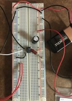
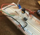
The attached photos show the present breadboard. Yes, I see that the red and black jack wires appear to be connected to the wrong rails; that's because I accidentally reversed those wires on the jack lugs. The biggest difference is the substitution of the resistor and cap between the jack output (the green wire) and pin 3. I also removed the grounding wire from pin 2 (inverting input) because the 12V DC power supply is non-inverting and connected to pin 3. It didn't help when pin 2 was grounded previously.
Before taking these new photos, I moved the guitar plug & jack while they were connected. This resulted in a hissing sound from the mini speaker. Now, with the hissing, when I pluck a string on my guitar, I can barely hear the note as part of the hissing, a very quiet part. With no connection between pins 1 and 8, the gain defaults to 20. If I add a resistor and cap between pins 1 and 8, that will increase the gain to 200; would that help?
P.S. I lowered my guitar gain knobs to about 5 and the stompbox gain to half way. This made no noticeable difference. This time, however, when I turned on the power supply, I heard a little pop from the speaker, which is what I want to hear from a guitar speaker when it is turned on. Still no real guitar sounds coming from the speaker.
P.S.S. Just now I turned off the power supply and the stompbox. When I next pulled the guitar plug from the jack, I heard some noise from the speaker. No idea where the power for this noise came from.
It was a 10K linear pot, marked B10K. To simplify things for troubleshooting, I temporarily removed the pot from the breadboard and now run the audio in thru a 4.7K 1/2W resistor and a 0.033uF 100V cap to the audio in pin (pin 3). The idea (remember, I'm a total noob) is to replace the pot with the equivalent of setting the volume pot to 5 out of 10 but without potential mistakes wiring the pot between the 1/4" jack and the chip. With this simpler setup, I read 8.26V DC on pin 3 (audio in), immediately behind this resistor and cap.
I tried substituting an 8ohm mini speaker; that made no difference.
I do hear a little crackling now when I insert the guitar plug and touch components with MM leads, e.g. when I check for DCV on the front and back legs of the speaker cap. Crackling seems to be progress, but still no cigar.
The attached photos show the present breadboard. Yes, I see that the red and black jack wires appear to be connected to the wrong rails; that's because I accidentally reversed those wires on the jack lugs. The biggest difference is the substitution of the resistor and cap between the jack output (the green wire) and pin 3. I also removed the grounding wire from pin 2 (inverting input) because the 12V DC power supply is non-inverting and connected to pin 3. It didn't help when pin 2 was grounded previously.
Before taking these new photos, I moved the guitar plug & jack while they were connected. This resulted in a hissing sound from the mini speaker. Now, with the hissing, when I pluck a string on my guitar, I can barely hear the note as part of the hissing, a very quiet part. With no connection between pins 1 and 8, the gain defaults to 20. If I add a resistor and cap between pins 1 and 8, that will increase the gain to 200; would that help?
P.S. I lowered my guitar gain knobs to about 5 and the stompbox gain to half way. This made no noticeable difference. This time, however, when I turned on the power supply, I heard a little pop from the speaker, which is what I want to hear from a guitar speaker when it is turned on. Still no real guitar sounds coming from the speaker.
P.S.S. Just now I turned off the power supply and the stompbox. When I next pulled the guitar plug from the jack, I heard some noise from the speaker. No idea where the power for this noise came from.
Attachments
Last edited:
Is that really an 8 ohm pot like the photo says? That right there would keep the sound out. The sample circuit has a 10k pot.
Oh, now I see what you mean. I don't know what I was thinking when I wrote that note. It was a 10K pot, as you noted. I took it out temporarily to simplify the wiring until the problem of no sound is solved. I'm going to have to sleep on it. ... I probably should simplify even further and follow an instructable on making a guitar amp in an Altoids tin. Or maybe I should get an adapter to use my iPhone as the audio source rather than my electric guitar, to clarify whether this is specifically a problem with using a guitar as the audio source.
-input (#2)........?
connected?
Pin 2 is for inverting input. Should pin 2 be connected to something other than ground if there is only non-inverting and no inverting input? The schematics that I have for LM386 amps have pin 2 grounded or unconnected.
I grounded 2 again. With pin 2 wired to ground, the speaker is silent when my guitar is silent. The speaker makes a tiny, barely audible sound/noise - not a discernible note - when I pluck a string. The sound of the unamplified steel string is a lot louder than the speaker output.
you should have a decoupling capacitor between supply and ground really.
Is that for sound quality only or does it affect whether this low-power amp would work at all?
Then I guess the speaker cap is working. With DC blocked, what should I try to measure with my MM to check whether my speaker is receiving the correct signal?
Is that when an oscilloscope is needed? A bench top version would be too pricey, but a mini pocket model might be affordable. However, I wouldn't have a clue in reviewing whether specs are appropriate for the full range of projects I might work on over time (the electronics bug has bitten me). Are any of the brands listed on the attached Amazon screenshot generally considered high-quality & dependable?
Attachments

Last edited:
Are you using an electric guitar?
Yes. Epiphone Les Paul with 2 volume knobs, 2 gain knobs, and a 15db 9V-powered volume boost when a specific knob is pulled up.
The lm386 needs about 400mv for full output, an electric guitar gives muck less. You need a preamp before the lm386, An op-amp circuit will do fine.
I assume that the stompbox, powered by a 9V wallwart, essentially functions as a preamp. When I plug the stompbox out line into the Marshall CODE50, turning the stompbox ON and OFF makes a substantial difference in the volume, so the stompbox appears to increase the signal.
With the stompbox immediately after the guitar, I measure 12.1V DC exiting the stompbox. Between the stompbox and pin 3 (audio in), I have a resistor and cap (together replacing a 10K linear pot temporarily). I measure 8.26V DC on pin 3, after the resistor and cap.
Aren't these readings immediately after the stompbox (before the resistor and cap) and on pin 3 (after the resistor and cap) sufficient?
Any reason NOT to remove the input resistor and cap, such that the guitar jack output at 12.1V DC feeds directly into pin 3? Remember, I myself came up with the idea of replacing a 10K pot used for volume with those resistor and cap, to eliminate any pot wiring problems temporarily while troubleshooting.
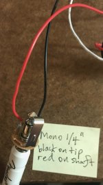
As for the wiring of the guitar jack, the tip is connected to pin 3 (at present, thru the resistor and cap between the stompbox and pin 3). The shaft is wired to ground. There is a third lug on this mono guitar jack; my guess is that it connects to a metal piece always touching the tip contact and may act as a shorting switch when no plug is in the jack (and maybe that short is always there, even when the guitar is plugged in?). The shaft is wired directly to ground. The tip is wired to pin 3 thru the resistor and cap. The + rail is connected directly to the third lug, the one apparently shorting to ground all the time. Since I have the stompbox providing power to the guitar plug (or for other reasons), should I substitute a 2-lug jack and omit the present connection to the + rail, connecting only the shaft to ground and the tip to pin 3 thru the resistor and cap?
Last edited:
Thank you, everyone, for all your pointers. I'm not sure exactly which change or changes earned the cigar, but when I attached a new 9V battery just now, the speaker came alive and I can now hear real guitar output as modified by the stompbox. I hear nothing with the stompbox turned off, so it appears to function as a preamp. With all the guitar knobs turned to 10 and the stompbox turned all the way up, the output thru a crappy little 29mm 8ohm speaker is plenty loud for practicing.
I kinda like the sound. It's a rather dirty mixture of what others who know more than I do might call distortion, overdrive, and/or crunch. There is a lot of constant background noise which detracts from the overall experience, so I will start making and testing changes one by one to see how they affect the sound and whether they kill the amp again.
For any other noobs like me who might choose an LM386/NTE823 as their first foray into DIY guitar amps, I will post my experience with each enhancement as implemented. I suppose I should start by creating and posting a schematic of the first functional design before making any changes. But first an on-off switch on the battery + wire so that I can stop detaching and reattaching the battery repeatedly.
My first working make of my little LM386/NTE823 amp is shown in the attached PDF file. I'm a total noob and wrote this for other total noobs.
The sound is very dirty. The first thing I will do is clean up the 9V battery current coming into the system.
N.B. This build did not work for my Les Paul with passive pickups, not even with a separate 9V battery in the guitar itself to provide a 10db volume boost, until I added a stomp box powered by a 9V wall wart. The stomp box apparently functions as a preamp. Although Epiphone says the LP has a preamp, it is not any kind of preamp which works with this build.
Attachments
...did not work for...
The R-C on the '386 output is critical for stability, and must be 10 ohms (not 10k).
Try a better volume pot connection and value.
You should really have a cap on pin 7, to reduce supply crap and set-up the internal gain structure properly.
A cap on pins 1 and 8 will make a WOW! difference of gain. But also begs for squealing in haywire builds. 500 to 200 ohms in series with this cap gets intermediate gains.
Attachments
The LM386 is prone to RF oscillations at about 13MHz, I find the IC is notorious for that. It can make it seem like it's distorted sounding and cause havoc as the speaker wires will radiate the RF too. Worse with increasing volume.
My last builds with it, only thing that would stop it was a 2.2uF ceramic cap right across the IC's power pins. If you had long leads or wires to the bypass cap, it would start up again at higher volume. Regardless if a Zobel or input cap was there.
edit: you also need bulk cpacitance like 220uF across power
Last edited:
Pin 2 is for inverting input. Should pin 2 be connected to something other than ground if there is only non-inverting and no inverting input? The schematics that I have for LM386 amps have pin 2 grounded or unconnected.
I grounded 2 again. With pin 2 wired to ground, the speaker is silent when my guitar is silent. The speaker makes a tiny, barely audible sound/noise - not a discernible note - when I pluck a string. The sound of the unamplified steel string is a lot louder than the speaker output.
Are you sure the amplifier has enough gain ?
A guitar puts out a very small signal and usually needs a pre amp before the amplifier.
- Status
- This old topic is closed. If you want to reopen this topic, contact a moderator using the "Report Post" button.
- Home
- Live Sound
- Instruments and Amps
- Why does this LM386 breadboard not work as a guitar amp?